
Pressure Sensor Signal Conditioning Circuit with Single Op-Amp
The pressure sensor signal conditioning circuit is designed to convert the raw output signal from a pressure sensor into a more usable form for further processing or display. The circuit typically includes components such as operational amplifiers, resistors, capacitors, and sometimes analog-to-digital converters (ADCs) to enhance the signal quality and ensure accurate readings.
In a basic configuration, the pressure sensor generates a voltage output that corresponds to the applied pressure. This output may be weak and susceptible to noise, necessitating signal conditioning. An operational amplifier (op-amp) can be employed to amplify the sensor's output signal. The gain of the op-amp can be adjusted using feedback resistors, allowing for calibration to the specific range of pressure measurements required.
Filtering may also be incorporated into the circuit to eliminate high-frequency noise. This can be achieved using passive RC (resistor-capacitor) filters or active filters that utilize additional op-amps. The choice of filtering method depends on the specific application and the frequency characteristics of the noise present in the environment.
For applications that require digital processing, the conditioned analog signal can be fed into an ADC. The ADC converts the analog voltage into a digital signal, which can then be processed by microcontrollers or digital signal processors (DSPs) for further analysis, display, or control purposes.
Overall, the pressure sensor signal conditioning circuit plays a crucial role in ensuring accurate and reliable pressure measurements by improving the signal quality and making it suitable for subsequent electronic processing.This is pressure sensor signal conditioning circuit. It is simple and inexpensive circuit because it has small geometry and simple pressure sensor. It just uses. 🔗 External reference
Related Circuits
This is a 25 Watt basic power amplifier designed to be relatively easy to build at a reasonable cost. It offers better performance than the standard STK module amplifiers commonly used in nearly all mass-market stereo receivers manufactured today. The...
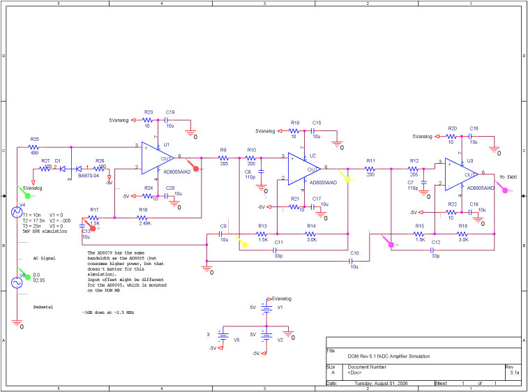
A bandwidth-limited amplifier shapes the waveform sampled by the 40 MHz high-speed pipeline Analog to Digital Converter (fast ADC, or fADC). It is well known that the shaping time is twice the time constant (peaking time) for each pole...
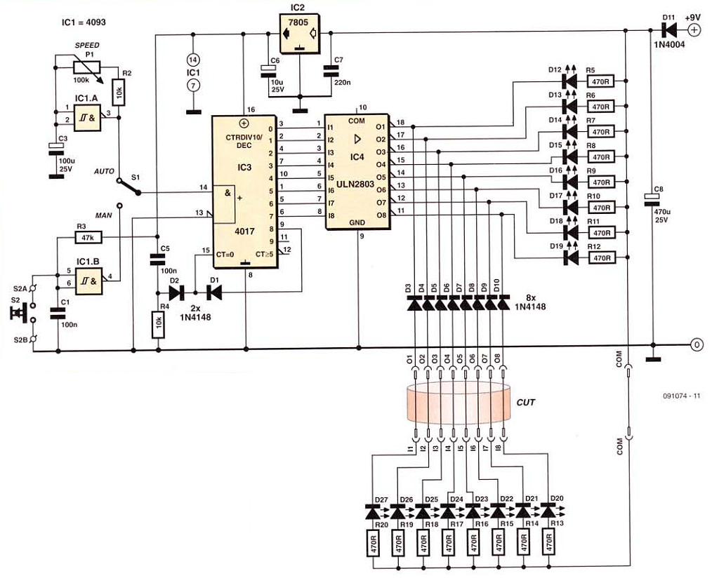
This network wiring tester consists of two components: a transmitter unit, which is powered and installed at the network's starting point, and a passive receiver unit that can be moved from socket to socket. Both units contain eight LEDs,...

I have been measuring V_A = 15, which appears to be incorrect. Additionally, I believe V+ is equal to 0 since the node below the 3-ohm resistor is grounded. Assistance is needed to begin solving this. Initially, I set...
This is an electronic muscle stimulator circuit that stimulates the nerves in the area of the body where electrodes are attached. It is useful for relieving pain. The electronic muscle stimulator circuit operates by delivering electrical impulses through electrodes placed...
A JFET-bipolar cascode circuit is designed to deliver complete video output for driving the cathode of a CRT. The configuration offers an approximate gain of 90. The cascode arrangement mitigates issues related to the Miller capacitance of the JFET...
Warning: include(partials/cookie-banner.php): Failed to open stream: Permission denied in /var/www/html/nextgr/view-circuit.php on line 713
Warning: include(): Failed opening 'partials/cookie-banner.php' for inclusion (include_path='.:/usr/share/php') in /var/www/html/nextgr/view-circuit.php on line 713