
Pro Maniac Guitar tube power amplifier
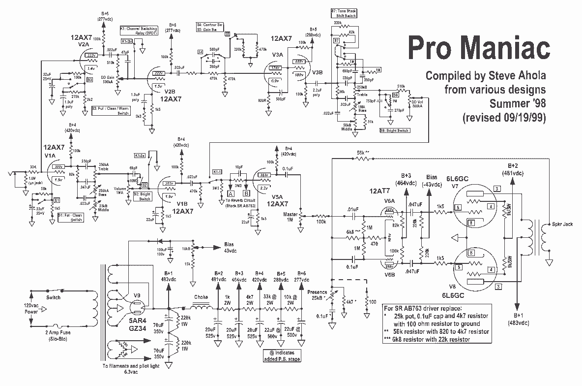
The circuit modification described involves specific component replacements and adjustments within the SR AB763 driver circuit. The original configuration includes a 25k potentiometer, a 0.1μF capacitor, and a 4.7kΩ resistor. The proposed changes suggest replacing these components with a 100Ω resistor connected to ground, which will likely alter the input impedance and affect the overall gain of the circuit.
In addition, a 56kΩ resistor is to be replaced with a combination of an 820Ω resistor in series with a 4.7kΩ resistor. This modification is intended to adjust the voltage divider ratio, potentially impacting the biasing conditions of the driver stage.
Furthermore, the circuit also mentions replacing a 6.8kΩ resistor with a 22kΩ resistor. This change will affect the feedback network and could lead to changes in the frequency response and stability of the circuit.
The overall effect of these modifications may result in improved performance characteristics of the SR AB763 driver, such as altered frequency response, gain adjustments, and potentially improved linearity or distortion levels. Careful consideration should be given to the impact of these changes on the circuit's operation and its integration into the broader system. Proper testing and validation should be conducted post-modification to ensure desired performance outcomes are achieved.For SR AB763 driver replace: 25k pot, 0.1uF cap and 4k7 resistor with 100 ohm resistor to ground. 56k resistor with 820 to 4k7 resistor. 6k8 resistor with 22k resistor 🔗 External reference
Related Circuits
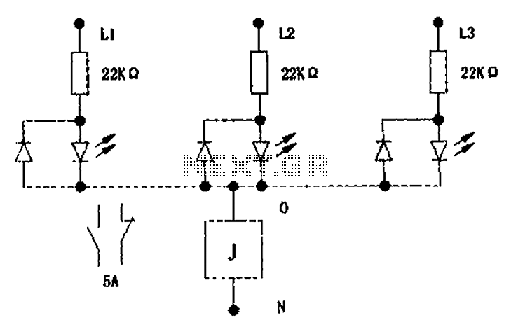
The circuit illustrated below activates a small relay (J) when there is an imbalance in any one phase of a three-phase circuit. This relay triggers an external control contact, which immediately disconnects the power supply to the main circuit...
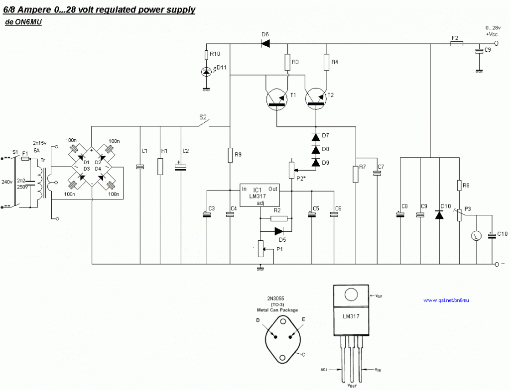
The following diagram is the schematic for a variable power supply that delivers an output voltage ranging from 0 to 28V at a current of 6/8 A. The component part list includes: R1 = 2.2 kΩ, 2.5 Watt; R2...
Miniature vacuum tubes utilizing cathodes made of high-field-emitting carbon nanotubes are being researched at Agere Systems in Murray Hill, NJ. A triode with an amplification factor of 4 has been developed, featuring an anode-cathode spacing of 220 µm, with...
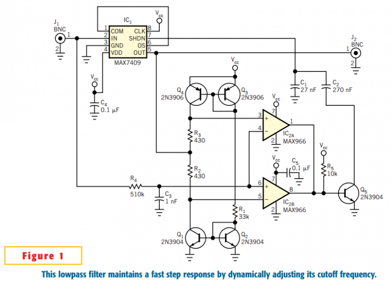
The circuit in Figure 1 accommodates lower cutoff frequencies without sacrificing the step-response time. A window comparator monitors the delta (difference) between the filter's input and output. When the delta exceeds ±50 mV, the filter increases its slew rate...
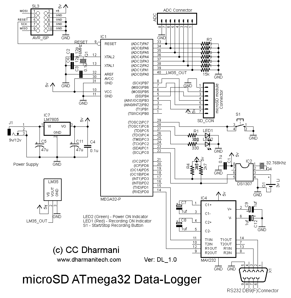
This article discusses the Gadgets, Gizmos, and Arduino (ATMega328). The content is straightforward and informative. The components mentioned in this article can enhance the understanding of the subject. For instance, readers can find and purchase components such as the...
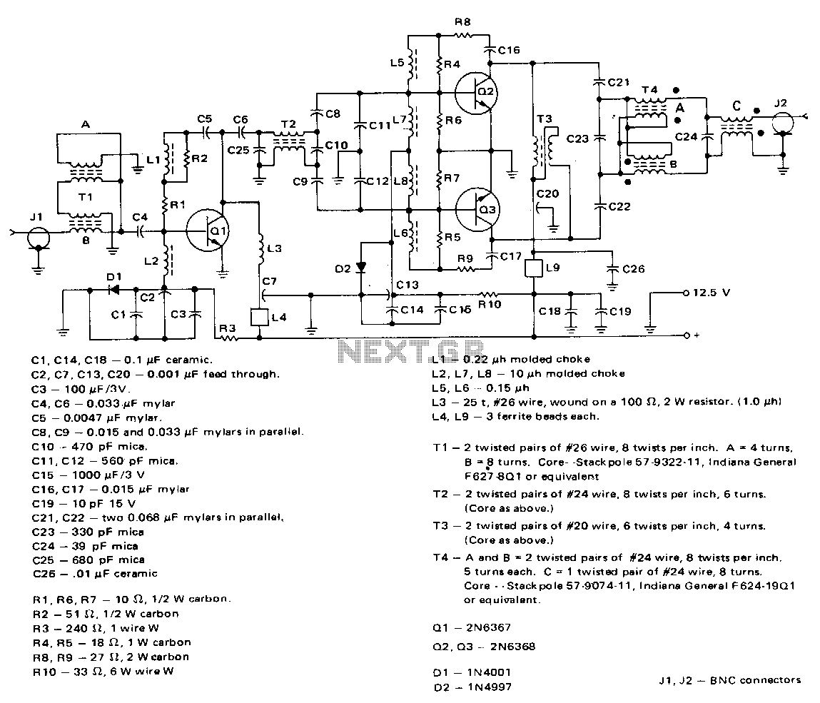
This amplifier employs a 2N6367 transistor as a driver along with a pair of 2N6368 transistors. The 2N6367 is rated for a maximum output of 9 W (PEP) and is required to deliver 5 W (PEP) at 30 MHz,...