
Programmable-power-supply
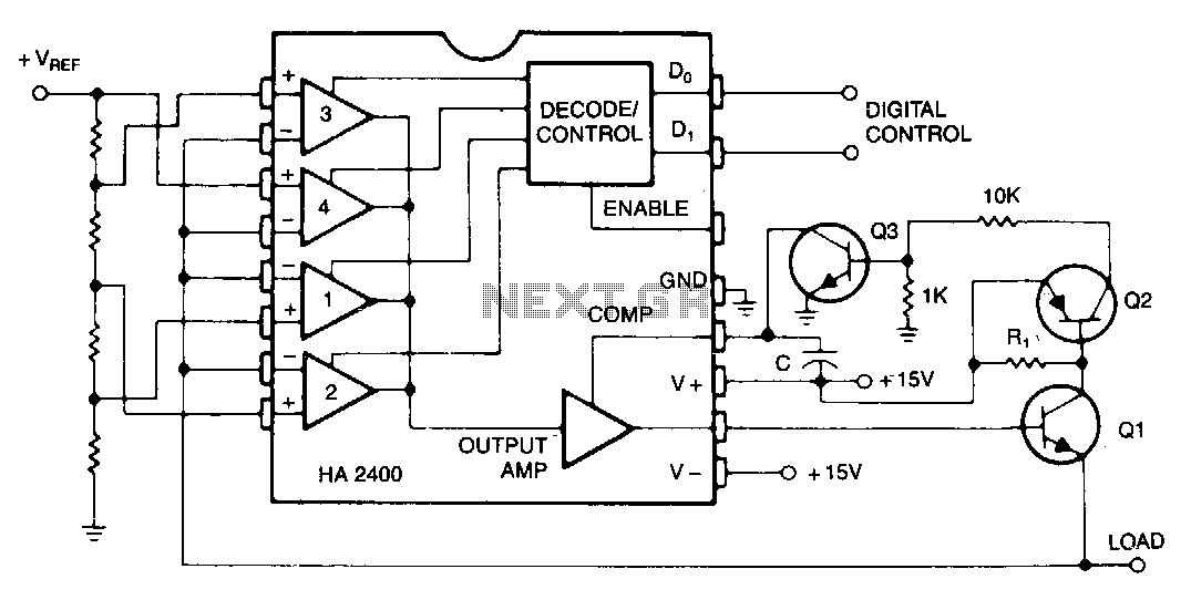
Many systems require one or more relatively low-current voltage sources that can be programmed to a few predetermined levels. The circuit presented generates positive output levels but can be modified for negative or bipolar outputs. Q1 serves as the series regulator transistor, selected based on the required current and power specifications. Additionally, R1, Q2, and Q3 comprise an optional short circuit protection circuit, with R1 designed to drop approximately 0.7 V at the maximum output current. The compensation capacitor, C, should be selected to maintain overshoot during switching within acceptable limits.
The described circuit functions as a programmable voltage source, suitable for applications requiring specific voltage levels with low current. The primary component, Q1, is a series pass transistor that regulates the output voltage. The choice of transistor is critical; it must handle the load current while dissipating minimal power to prevent overheating.
The optional short circuit protection circuit, consisting of R1, Q2, and Q3, enhances the reliability of the system. R1 is a current-sensing resistor that generates a voltage drop proportional to the load current. When this voltage reaches approximately 0.7 V, it activates Q2, which in turn controls Q3. This action disconnects the output from the load, preventing damage from excessive current draw.
The compensation capacitor, C, plays a vital role in stabilizing the feedback loop of the regulator. Proper selection of this capacitor is essential to minimize overshoot and ringing during transient events, such as sudden load changes. The value of C should be determined based on the specific characteristics of the circuit, including the bandwidth and phase margin requirements.
Overall, this circuit design provides a robust solution for generating low-current, programmable voltage levels while ensuring protection against short circuits and maintaining stability during operation.Many systems require one or more relatively low-current voltage sources which can be programmed tna few predetermined levels. The circuit shown above produces positive output levels, but could be modified for negative or bipolar outputs.
Q1 is the series regulator transistor, selected for the required current and power capability. R1, Q2, and Q3 form an optional short circuit protection circuit, with R1 chosen to drop about 0. 7 V at the maximum output current. The compensation capacitor, C, should be chosen to keep the overshoot, when switching, to an acceptable level. 🔗 External reference
Warning: include(partials/cookie-banner.php): Failed to open stream: Permission denied in /var/www/html/nextgr/view-circuit.php on line 713
Warning: include(): Failed opening 'partials/cookie-banner.php' for inclusion (include_path='.:/usr/share/php') in /var/www/html/nextgr/view-circuit.php on line 713