
Project: PC Power-on Combination Lock? |? O J Ford
The PC Power-on Combination Lock (PCPCL) is an innovative security device designed to enhance the physical protection of desktop computers. This circuit operates on the principle of requiring a specific combination of inputs to allow the power-on sequence of the computer. The primary component of the PCPCL is a PIC microcontroller, which serves as the central processing unit, effectively managing the input combinations and controlling the output to the power supply of the PC.
The circuit design begins with the input mechanism, where a keypad or a series of switches is used to enter the password. Each switch corresponds to a binary input, which the microcontroller reads and processes. The PIC microcontroller is programmed to recognize the correct sequence of inputs, and upon successful entry, it sends a high signal to the output, allowing power to flow to the computer's power supply unit.
To enhance security, the design includes a feature that triggers an alarm after three consecutive incorrect attempts to enter the password. This is achieved through integrated software logic within the microcontroller, which counts the number of attempts and activates an output pin connected to an alarm circuit.
The physical housing of the PCPCL is constructed from acrylic, which not only provides a visually appealing aesthetic but also facilitates modularity. The main control board and the output daughter board are designed to be separate, allowing users to customize the output options according to their needs. The acrylic casing was precisely cut using a laser cutter, ensuring that the components are securely mounted while maintaining a professional appearance.
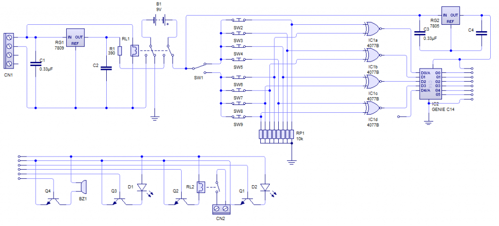
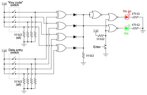
In terms of electrical components, the circuit utilizes XOR gates to manage the logic for the password entry system. This allows for flexibility in changing the password by simply switching the inputs, a feature made possible by the PIC microcontroller's ability to handle multiple input configurations despite a limited number of pins.
Overall, the PCPCL exemplifies a well-thought-out approach to improving computer security through hardware solutions, demonstrating the integration of microcontroller technology, modular design, and user-friendly features. The project not only fulfills the educational objectives but also addresses real-world security concerns for small businesses, making it a significant contribution to the field of electronics and security systems.I designed the PC Power-on Combination Lock (PCPCL) last year for my GCSE Systems & Control project. The exam board stated that we must design a product under the broad category of `Safety and Security`. I already had in mind some ideas for what I wanted to do, so I was glad that not only was the specification rather vague, but also that it exactl
y described the topic of what I had in mind. I wanted to design a product that would increase the level of security protecting a desktop PC. Software passwords are all very well, but a way around them is just a Google search or Linux Live CD away. Clearly for the average user, that`s enough by way of deterrent, but I was interested in something for small businesses, whose PC`s may contain some sensitive information, but lack enterprise-level security.
I decided my project should entail a hardware level of security, that prevents the computer from even turning on without a supplied password. With that in mind, I wrote my own design brief and specification along those lines laying out some more ideas for what the device absolutely must do, what it should do, and some looser could do` ideas.
Originally, I was using combinational logic from independent gates to make just one combination of four inputs send the output, Q high. However, later, this proved messy and I ended up using a PIC microcontroller from Microchip to nip it in the bud with just a single IC, whereas using several gates obviously involved several ICs, which caused a problem trying to minimise PCB size.
This wasn`t just a cost-cutting exercise, I was quite strict from the outset that the device should fit within the smaller ATX drive bay standard (3. 25 ³). Using a PIC had other advantages, too. I was able to incorporate almost all functionality of the circuit onto a single device such as the alarm after three incorrect entry attempts, for which I was previously using D-type flip-flops.
The next task was to design and fabricate a case for the electronics. I decided to use acrylic; I had originally wanted to use aluminium for aesthetic and grounding purposes, but I decided it would over-complicate the project, and be tough to achieve the look and design of the front panel which I had in mind. I did this partly for modularity the outputs daughter board which I kept separate from the main power and control board could easily be switched by an end-user for different ouptput possibilities.
It took some experimenting to find an appropriate speed and power for the laser-cutter to indent the acrylic by no more than 2mm, but once I had it honed in on some scrap pieces, it worked a treat and proved a successful method for mounting the PCBs. I had a near-project-death experience when I was applying the finishing touches, though. I was heat-shrinking the final (of eight) switch wires from the PCB to front panel, when it occurred to me that I had not checked the switch type.
I had pulled them off-the-shelf, assuming they were push-to-make`. Sod`s Law would dictate that they were not, and as such carried out exactly the opposite to the intended function. Luck would have it that my final circuit designentailed each switch being XOR`d with it`s opposite number` (I had included two banks to allow the correct code to be changed at the flick of a switch, as the PIC I used does not have enough input pins to connect all eight) so I was able to simply switch out the 4070 (XOR) gate for a 4077 (XNOR).
I received 175 marks of a possible 180, and after combining with the exam I achieved a final result of an A* at 100% normalised UMS. The project was also assessed by BSA, and I was awarded a Silver CREST award for my work. On advice from my school, I also entered the PCPCL and accompanying portfolio in the Valter Prize competition in which I achieved third place, awarded by the IET.
🔗 External reference
Related Circuits
A combination of a common-source grounded emitter amplifier and a common emitter amplifier. The input impedance of the common emitter amplifier is in the range of 1.03 fl. Directly connecting the FET drive can be challenging; however, utilizing an...
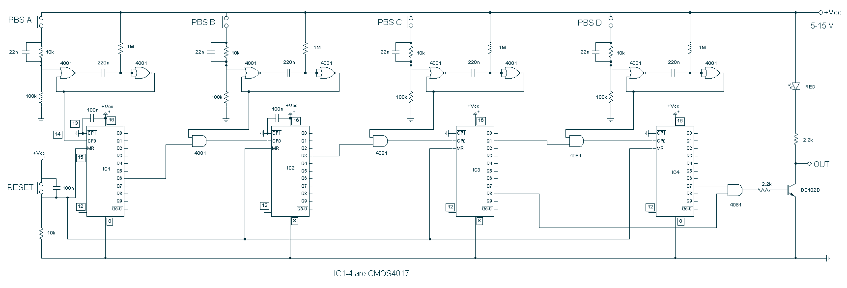
The circuit above makes use of the CMOS 4017 decade counter IC. Each depression of a switch steps the output through 0 - 9. By coupling the output via an AND gate to the next IC, a predefined code...
A 1996 Ford Explorer has non-functional headlights. The vehicle has operational low beams and interior lights. The owner has replaced the bulbs, checked the fuses, relays, and light switch, yet the headlights remain inoperative. Suggestions are requested to identify...
This experiment can be constructed using a single 8-position DIP switch, although utilizing two switch assemblies may facilitate a better understanding of the concept. One switch assembly is designated to hold the correct code for unlocking the lock, while...

The AV combination as depicted in the diagram involves the first stage using the Philips TDA1029, which functions as a four-input switching signal processor. The second stage employs the NE5532 as a preamplifier, while the B of the NEC,...
The simple circuit of Fig.1 emulates a similar conjuring trick which sells for hundreds of Pounds. The trick seems to do the almost-impossible from an electronic point of view, let alone from the point of view of common sense....