
Proportional-temperature-controller
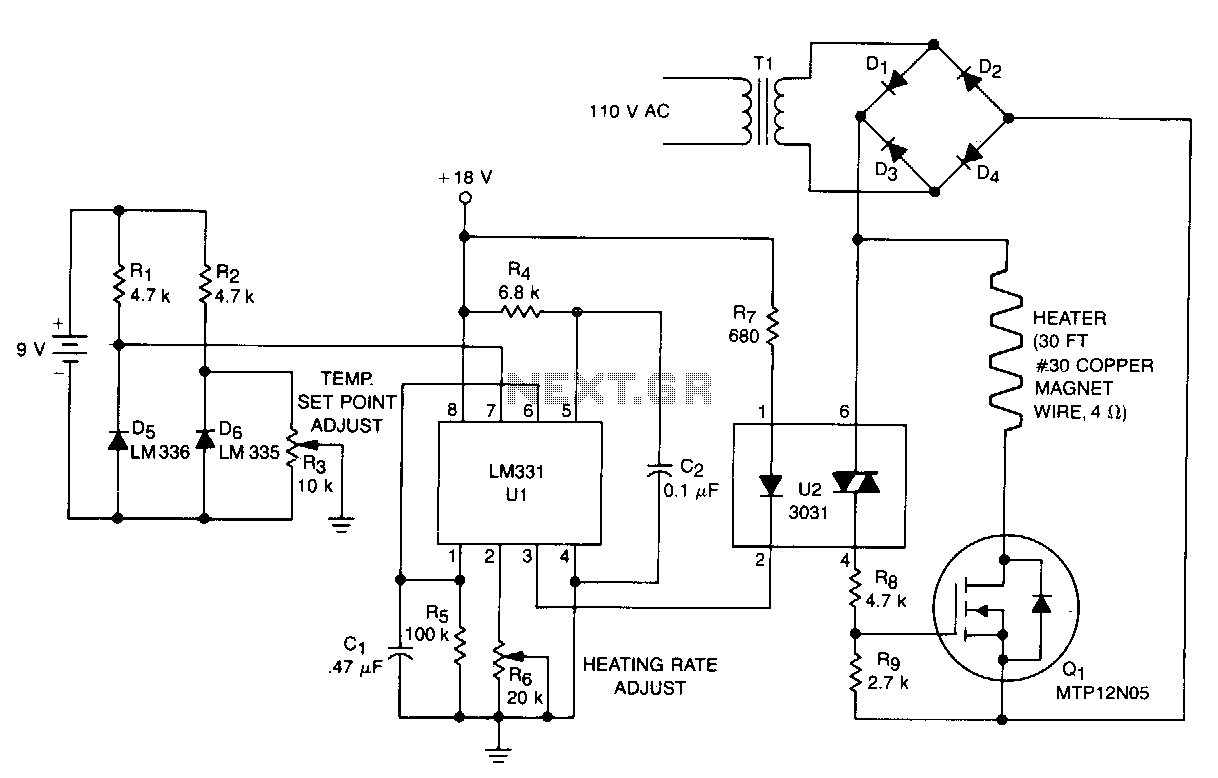
This temperature controller functions as a pulse snatching device, enabling it to operate at its own speed and activate at the zero crossing of the line frequency. The zero crossing activation minimizes the generation of line noise transients. A TMOS Power FET, Q1, is utilized to control the heater. The temperature sensor D6 generates a DC voltage that is proportional to the temperature, which is then fed into a voltage-to-frequency converter, U1. The output from U1 is a pulse train that corresponds to the temperature offset, which is directed to the input of the triac optoisolator, U2. The anode supply for the triac is a 28 V peak-to-peak, full-wave rectified sine wave. The optoisolator combines the pulse train from U1 with the zero crossing of U2's anode supply, providing a gate turn-on signal for Q1. Consequently, the TMOS power FET Q1 can only activate the heater at the zero crossing of the applied sine wave. The maximum temperature, constrained by the sensor and the insulation of the wire, is 130°C for the components specified.
The temperature controller circuit is designed to efficiently manage the heating element while minimizing electrical noise. At the core of this design is the TMOS Power FET (Q1), which serves as a switching device for the heater. It is activated only at the precise moment when the AC line voltage crosses zero, a technique known as zero crossing turn-on. This method is critical as it reduces electromagnetic interference (EMI) that can arise from abrupt switching.
The temperature sensor (D6) is a key component in this system, providing real-time feedback on the temperature. It outputs a DC voltage that varies with temperature, which is then processed by the voltage-to-frequency converter (U1). This IC translates the varying voltage into a frequency-modulated signal, producing a pulse train that is directly proportional to the temperature offset. This pulse train is essential for controlling the timing of the heater activation.
The triac optoisolator (U2) plays a vital role in isolating the control circuitry from the high-voltage AC line. It receives the pulse train from U1 and combines it with the zero crossing of its anode supply, effectively synchronizing the control signal with the AC waveform. This synchronization ensures that Q1 is only triggered to turn on the heater when the line voltage is at zero, further minimizing noise and ensuring safe operation.
The anode supply for the triac, specified as a 28 V peak-to-peak, full-wave rectified sine wave, provides the necessary voltage levels for the optoisolator to function correctly. The system is designed to handle a maximum temperature of 130°C, a limit determined by the specifications of the temperature sensor and the insulation properties of the wiring used in the circuit.
This temperature control circuit is particularly suitable for applications requiring precise temperature regulation while maintaining low electrical noise, making it ideal for sensitive electronic environments.This temperature controller operates as a pulse snatching device, which allows it to run at its own speed and tum on at the zero crossing of the line frequency. Zero crossing tum-on reduces the generation of line noise transients. TMOS Power FET, Ql, is used to tum on a heater. Temperature sensor D6 provides a de voltage proportional to temperature that is applied to voltage-tofrequency converter Ul.
Output from Ul is a pulse train proportional to temperature offset that is applied to the input of triac optoisolator U2. The anode supply for the triac is a 28 V pk-pk, full-wave rectified sine wave. The optoisolator ORs the pulse train from Ul with the zeroTrossing of U2"s anode supply, supplying a gate tum on signal for Ql. Therefore, TMOS power FET Ql can only tum the heater on at the zero crossing of the applied sine wave.
The maximum temperature, limited by the sensor and the insulation of the wire, is 130°C for the components shown. 🔗 External reference