
proximity alarm circuit

The circuit described employs a configuration of inverters (U1a and U1b) to create a relaxation oscillator, utilizing the resistive-capacitive (RC) timing method. The frequency of oscillation is dictated by the resistor R1 and the capacitors C1 and C2, alongside the inherent characteristics of the integrated circuit. The output from the oscillating circuit produces a pulsed DC voltage, which is conditioned through capacitors C3 and C4 and diode D2, ensuring that the voltage is stable and suitable for further processing.
The third inverter (U1c) serves as a buffer and signal conditioner, maintaining a low output state as long as the oscillation persists. This state prevents transistor Q1 from turning on, thereby silencing the buzzer (BZ1). The sensitivity of the circuit is adjustable through capacitors C1 and C2; when these are set to their optimal values, the pickup plate can detect proximity, triggering an alert when a hand is within 3 to 5 inches.
To calibrate the circuit, the capacitors should initially be set to half of their maximum capacitance. Upon powering the circuit, it is expected that oscillation occurs without audible output from the buzzer. Fine-tuning is necessary for optimal performance; using a non-metallic screwdriver, one capacitor should be adjusted downward until oscillation ceases, at which point the buzzer should activate. A slight adjustment back towards the original setting will restore oscillation, marking the circuit's most sensitive configuration. This process ensures that the circuit can effectively detect proximity while minimizing false triggers.Inverters U1a and U1b are connected in a simple RC oscillator circuit. The frequency is determined by the values of R1, C1 C2 and the internal characteristics of the integrated circuit. As long as the circuit is oscillating, a positive dc voltage is developed at the output of the voltage-couple circuit: C3, D2 and C4.
The dc voltage is applied tothe input of U1c-the third inverter amplifier-keeping its output in a low state, which keeps Q1 turned off so that no sound is produced by BZ1. With C1 and C2 adjusted to the most sensitive point, the pickup plate will detect a hand 3 to 5-inches away and sound an alert. Set C1 and C2 to approximately one-half of their maximum value and apply power to the circuit. The circuit should oscillate and no sound should be heard. Using a non-metallic screwdriver, carefully adjust C1 and C2, one at a time, to a lower value until the circuit just ceases oscillation: Buzzer BZ1 should sound off.
Back off either C1 or C2 just a smidgen until the oscillator starts up again-that is the most sensitive setting of the circuit. 🔗 External reference
Related Circuits
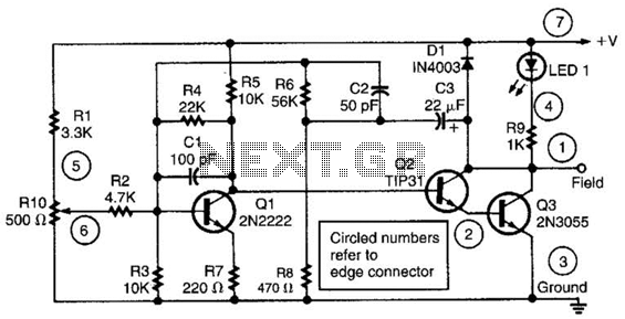
This alternator regulator utilizes a 3-transistor DC amplifier and is designed for a pulled-up field system, where one side of the alternator field returns to the +12V supply, and the other end is pulled toward ground. The circuit monitors...
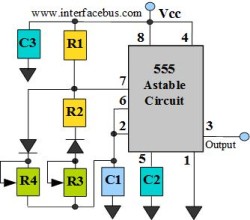
The astable multivibrator circuit lacks a stable state. In the absence of an external signal, the internal transistors alternately switch between cutoff and saturation at a frequency determined by the RC time constants of the coupling circuits. Therefore, an...

A 555 timer (IC1) controls a 4017 CMOS decade counter. The first four outputs of the 4017 drive a CA3079 zero-voltage switch. Pin 9 of the CA3079 is utilized to inhibit output from pin 4, effectively disabling the stream...
This audio-video circuit enables wireless audio and visual transmission to a television. The television functions as a receiver, eliminating the necessity for a separate monitor. It can also be connected to a VCR or CCD camera, and can be...
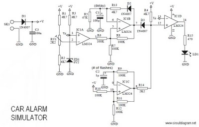
This is a car alarm simulator that uses an LED as a simulation output. This simple circuit can indicate whether a car is running by detecting the voltage difference when the car is on and off. When the car...
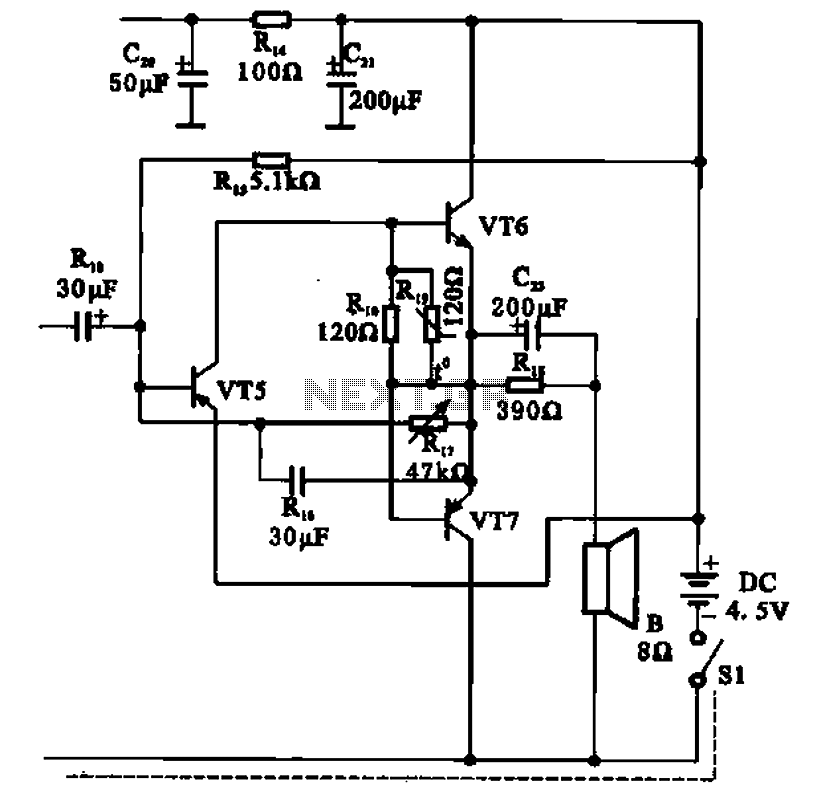
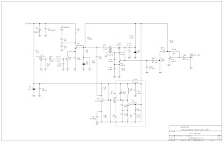
The transistor radio features a common output transformerless (OTL) power amplifier circuit. The VT5 component serves as the bias resistor for the driver stage. VT6 and VT7 form a complementary symmetry configuration, with VT6 being a germanium NPN transistor...