
Proximity Camera Head (A2047) Manual
Marked are (1) the eight-w ay flex socket for connection to a TC255P Minimal Head (A2016), and (2) the LWDAQ device socket. The flex socket pin one has a square pad on the connector footprint. The A2047 connects to a LWDAQ driver (such as the A2037 ) or LWDAQ multiplexer (such as the A2046 ) with a LWDAQ cable. The A2047 connects to the image sensor through a flex cable. The image sensor is mounted upon any TC255P Minimal Head ( A2016 ). The flex cable is a 1-mm pitch, 8-way flat cable. We have operated the A2047 with flex cables up to 450 mm long, but we notice an increase in image noise and some loss of contrast at such lengths.
In almost all our instruments, the flex cable is less than 100 mm long. The Inplane Sensor Head (A2047T) has the same shape as the Inplane Sensor Head ( A2036A ). The A2047A is a long, thin version of the same circuit, designed for the long, thin Proximity Camera. The A2047C is identical to the A2047A except that its output amplifier gain is higher to suit readout of the TC237B.
Resistors R26 and R29 are 3. 3 k © instead of 1. 0 k ©. We designed the A2047 for use in the ATLAS end-cap muon spectrometer alignment system. The circuits read out chessboard images as part of Rasnik Instrument. For a description of Rasnik images and how we analyze them, see Rasnik Analysis. Table:Command Bit Allocation on the A2047. An "X" means the command bit serves no function. The signals are DCEN for direct clock enable, SRGD for serial register gate digital, SAGD for storage area gate digital, IAGD for image area gate digital, ABGD for anti-blooming gate digital, ABEN for anti-blooming enable, and LB for loop back. The A2047 does not provide anti-blooming. The A2047 is asleep when it powers up, and after a sleep job. To measure the propagation delay of signals traveling from the driver to the A2036 and back again, we execute the loop job and read the loop time out of the driver.
The A2047 is functionally equivalent to the Inplane Sensor Head ( A2036B ). It provides image capture from a a TC255P. Images we obtain from an A2047 tend to be brighter than those we obtain with an A2036, because of improvements in the way the A2047 handles the analog pixels voltages. You can compare images obtained from various sensor heads in the Image Contrast section of the A2036 Manual.
You will find a discussion of the data acquisition steps required to control and read out the A2047 in the Operation section of the same A2036 Manual. The Inplane Sensor Head (A2047T) is a drop-in replacement for the Inplane Sensor Head ( A2036B ), but its internal circuits are more resistant to radiation.
We designed the A2036 in 2002, tested it in ionizing and neutron radiation over the next two years, observed it to be inadequately resistant to ionizing radiation, and designed the radiation-hardened (or "rad-hard") Proximity Camera Head (A2047A) in 2004. In 2012, both circuits have seen five years of installation and testing, followed by three years of use in the ATLAS detector.
For a summary of our radiation tests up at the end of 2002 see Pre-Production Radiation Tests. The A2047 replaces a MAX6329 low drop-out regulator with a transistor-diode regulator. The MAX6329 requires only the +5-V supply to produce 3. 3-V logic power, and it provides a power-up reset signal. But the MAX6329 contains a band-gap reference voltage, and this band-gap is affected by ionizing radiation. In our tests, the MAX6329 output rose by 10 mV/krad, or 1 V after 100 krad. The A2047 replaces the MAX6329 with a 3. 3-V regulator made out of a chain of six diodes and bipolar transistors. This regulator appears unaffected by 100 krad. But it does not provide a power-up reset signal, and it requires 300 A of current from the +15-V power supply.
This reliance of the 3. 3-V logic power upon the +15-V power means that the A2047 internal logic will function only so long as the +15-V power supply is above 10 V. There were many times during the construction and testing of the ATLAS detector that we suspected an interaction between the +15-V and 3.
3-V supplies to be the cause of power-up problems. But it turned out that these problems had other cauases. In the end, therefore, this 3. 3-V rad-hard regulator has been a success. The six series PN diodes provide a 3. 9-V drop, which biases the base of an NPN transistor, and so provides the 3. 3-V logic supply voltage. For constant current, the voltage across PN diodes dropes by approximately 2. 4 mV/ °C. This change in logic supply with temperature limits the recommended operating temperature of the A2047 to 0 °C to 75 °C. Outside this temperature range, the LVDS transceiver may stop performing properly and the clock signals provided to the image sensor may be too far away from their optimal values.
The A2047 needs a power-up reset signal, but all commercially-available power-up reset generators use band-gap references to monitor the power supply voltage. We implement a crude, rad-hard power-up reset with a 1 F capacitor and 10 k © resistor (C9 and R22 in the A2047 schematic ).
At power-up, the reset voltage is zero and rises with time constant 10 ms to 3. 3 V. This circuit works well, provided that the 3. 3-V power asserts itself sharply, within 1 ms. An error in the design of the LWDAQ Driver ( A2037 ) led to the Reset Failure problem, in which the power logic power supply took 60 ms to establish itself, thus rendering our 10-ms reset time constant ineffective. This power-up reset failure caused many problems in large LWDAQ systems, such as Cold Start and Mask Burn-Out.
When we fix the error in the A2037, which is simply a matter of removing one capacitor, the logic power supply rises in less than a millisecond, and the reset is reliable. In the end, therefore, this rad-hard reset circuit was a success. The A2036 switched its power supplies with a DG411DY quad analog switch. We observed these switches to fail somewhere between 20 krad and 100 krad. The A2047 replaces analog switches with discrete mosfets and bipolar transistors. We use the NDS356AP and NDS355AN are p- and n-channel mosfets with on-resistance less than 200 m ©. We used this circuit to measure the threshold voltage of the NDS355AN before and after irradiation. Before irradiation, the threshold voltage of 300 devices was 1. 5 ±0. 1 V. After 100 krad of ionizing radiation, the threshold voltage of ten devices had dropped to 0. 6 ±0. 1 V. Even if the initial threshold voltage was the minimum 1. 0 V given in the data sheet, we can still drive the mosfets with 3. 3-V logic levels. Thus we use mosfets in the Bar Head ( A2044 ) to select temperature sensors with logic levels. Transistors Q1, Q2, and Q4 are mosfets that switch the ±15-V power supplies. Transistor Q3 could be an n-channel mosfet also, but is instead we use an NPN transistor with integrated base resistor.
We decided to use the NPN transistor to guarantee that we could turn off the power supplies, even if later reels of mosfets proved to be more vulnerable to radiation than our first reel. Our tests of the A2047 showed no failure of the power switches at 100 krad. But our test of the A2044 did show Central to the operation of all LWDAQ Devices is the timing of its command receiver.
On the A2047 and A2036, this timing is provided by a dual monostable multivibrator, the 74VHC123. The multivibrator consumes a few microamps until it receives a logic transition, and generates a pulse of 125 ±10 ns. In the A2036 we found them to be fully-functional after 30 krad, but we observed one failure out of four circuits at 100 krad.
The failed circuit would not issue a pulse. We observed no shift in the length of the pulses at 100 krad or 30 krad. We knew of no other way to generate such rapid pulses with such low quiescent and active current, other than some of the newer zero-power programmable logic chips. We hesitated to embark upon lengthy radiation testing of programmable logic chips, so we kept the 74VHC123 in the A2047 design, and all subsequent ATLAS command receivers.
Subsequent tests confirmed that the 74VHC123 is unaffected by 30 krad. We are confident that the A2047 can endure a slow dose of 20 krad without failure, and without its sleep state current consumption from the +5V power supply rising above 5 mA, which is the maximum permissable by the LWDAQ Specification. The A2036, on the other hand, draws 5 mA from the +5V power supply after only 5 krad. In the A2047, the rise in current consumption is due to damage to the logic circuits. In the A2036, the rise is due to damage to the rising regulator output voltage causing current to flow through the clamping zenar diode Z1 (see here ).
For a discussion of image geometry, and how to translate between points in the image sensor and points in the image on our computer screen, see the Image Geometry section of the TC255P Minimal Head ( A2016 ) Manual. For instructions on finding Pin One on a TC255P, see the Pin One section of the same manual. The A2047 provides brighter images than its predecessor, the A2036. We discuss the image quality provided by our various TC255P readout circuits in the Image Contrast of the A2036 Manual.
🔗 External reference
Related Circuits
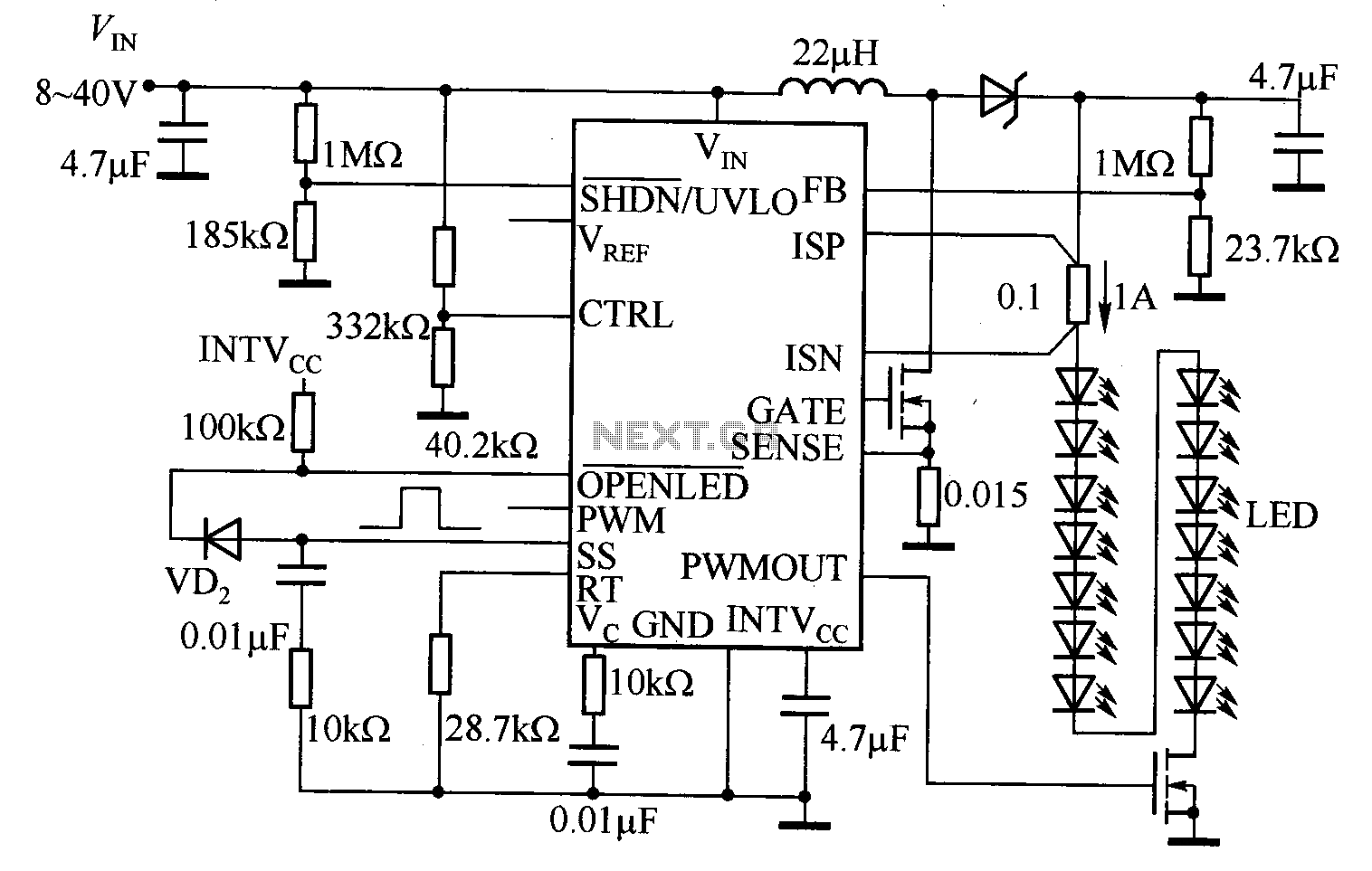
The LT3755 is utilized for high-side current sensing in LED strings, enabling flexible programming and control. It supports a PWM input that allows for a dimming ratio of up to 3000:1, while the CTRL input offers additional analog dimming...
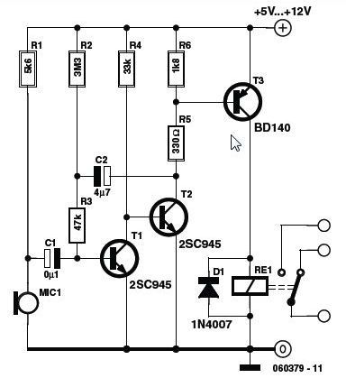
This circuit features a simple, highly sensitive capacitive ON/OFF switch pad that changes the state of a latch and activates an LED without requiring physical contact. The pad can be insulated, and a range of 12mm is easily achievable...
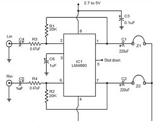
The LM4880 is a dual audio HiFi amplifier integrated circuit from National Semiconductor. This headphone amplifier circuit is specifically designed to produce high-quality audio output with a minimal number of components. The LM4880 integrated circuit is capable of delivering...
SW1 bypasses the crossfeed network. I have reconfigured the original crossfeed schematic so that now the 100k resistor always bridges the bypass switch and thereby reduces any 'crackle' or 'click' or whatever you may call them. Don't omit these...
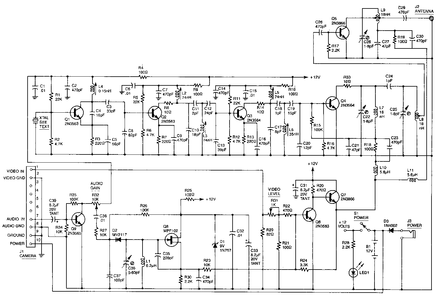
This high-performance video camera link transmits signals from a video camera to a VCR or from a VCR to TVs throughout a home. The initial stage of the RF chain features a crystal-controlled oscillator, Q1, operating at a frequency...
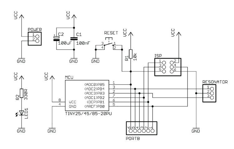
This handy breadboard header for ATTiny 25/45/85 microcontroller is a new design based on the original idea from Tinkerlog. Maybe the most useful feature is that it can provide power to the vertical breadboard strips while connecting all six...
Warning: include(partials/cookie-banner.php): Failed to open stream: Permission denied in /var/www/html/nextgr/view-circuit.php on line 713
Warning: include(): Failed opening 'partials/cookie-banner.php' for inclusion (include_path='.:/usr/share/php') in /var/www/html/nextgr/view-circuit.php on line 713