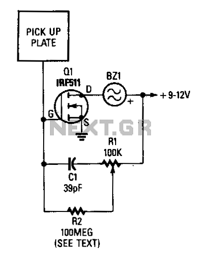
Proximity-switch

A 3x3-inch piece of circuit board, or a similarly sized metal object, serves as the pick-up sensor connected to the gate of Q1. A 100 MΩ resistor, R2, isolates Q1's gate from R1, ensuring that the input impedance remains very high. If a 100 MΩ resistor is unavailable, five 22 MΩ resistors can be connected in series to achieve the required resistance for R2. Increasing the value of R2 can enhance sensitivity further. Potentiometer R1 is set to the point where the piezo buzzer begins to sound, then adjusted back to where the sound stops. Fine-tuning R1 will assist in achieving optimal sensitivity for the circuit. R1 can also be set so that the pick-up must be physically contacted to trigger the alarm sounder. A relay or another current-consuming component can replace the piezo sounder, allowing control of various external circuits.
The described circuit configuration employs a pick-up sensor that is crucial for detecting external stimuli. The sensor's connection to the gate of transistor Q1 allows for the amplification of the signal generated by the pick-up sensor. The use of a high-value resistor R2 is critical in maintaining high input impedance, which is essential for minimizing loading effects on the sensor. This characteristic enables the circuit to detect even minute changes in the environment, thus enhancing the sensitivity of the overall system.
The potentiometer R1 serves as a variable resistor, allowing for precise adjustments to the threshold at which the piezo buzzer activates. This feature is particularly useful in applications where sensitivity needs to be tailored to specific conditions or environments. The ability to adjust the resistance makes it possible to set the circuit to be responsive only when significant contact is made with the pick-up sensor, which can help to prevent false alarms.
In scenarios requiring higher power output, the circuit can be modified to include a relay or other components that demand more current than the piezo sounder. This flexibility allows the circuit to interface with various external devices, thus broadening its application range. Overall, the circuit design provides a robust solution for detecting stimuli and triggering alarms or other actions based on the presence of external factors.A 3-x -3-inch piece of circuit board, or similar size metal object which functions as the pick-up sensor, is connected to the gate of Ql. A 100-MD resistor, R2, isolates Ql"s gate from Rl, allowing the input iropedance to remain very high.
If a 100MO resistor cannot be located, just tie five 22-MO resistors in series and use that combination for R2. In fact, R2 can be made even higher in value for added sensitivity. Potentiometer Rl is adjusted to where the piezo buzzer just begins to sound off and then carefully backs off to where the sound ceases. Experimenting with the setting of Rl will help in obtaining the best sensitivity adjustment for the circuit.
Resistor Rl can be set to where the pick-up must be contacted to set off the alarm sounder. A relay or other current-hungry component can take the place of the piezo sounder to control most any external circuit.