
pull up and pull down resistor
In digital electronics, understanding the behavior of floating inputs is crucial for reliable circuit operation. A floating input is one that is not connected to a definite voltage level, and it can pick up noise, leading to unpredictable states in digital logic devices. To avoid this, pull-up and pull-down resistors are employed.
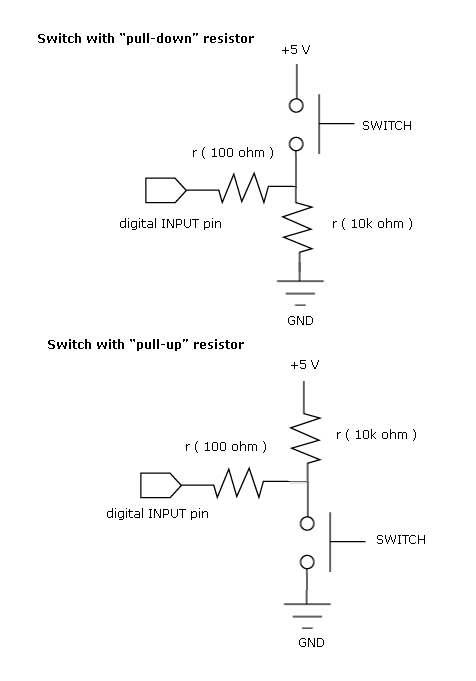
In a pull-up resistor configuration, the resistor is connected between the input pin of the logic IC and the positive supply voltage (Vcc). This ensures that when the input is not actively driven low, it defaults to a high state (logic 1). Conversely, in a pull-down configuration, the resistor connects the input pin to ground, ensuring that the input defaults to a low state (logic 0) when not driven high.
The choice of resistor value is important for balancing power consumption and response speed. A 10 kΩ resistor is commonly used as it provides a good compromise between current draw and response time. Lower resistor values will result in higher current consumption, while higher values may lead to slower response times due to increased resistance to rapid voltage changes.
In summary, proper handling of floating inputs through the use of pull-up or pull-down resistors is essential in digital circuit design to ensure predictable behavior and efficient power management.Most of the beginners in digital electronics assume that the hanging input is a logic 0. Then, that`s a misconception. They are neutral state which can be a logic 0 or a logic 1. This will bring chaos on your circuit operation. As you can see, in each case there is a default input. For a pull-up, the default input to the logic IC is 1. And for the pull-down, the logic is 0. The resistor also provide a current limiting function thus affecting power consumption of the input section. 10kohms is the commonly value but any value can be use depending on your application. 🔗 External reference
Related Circuits
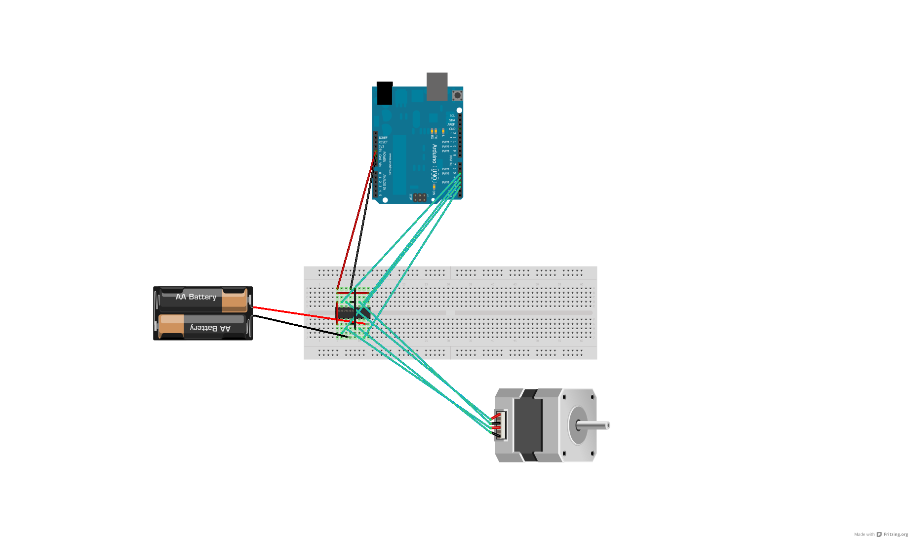
After conducting some research, it was found that voltage can be adjusted using either a voltage regulator chip or resistors. Several scenarios require reducing the voltage for motors, prompting a question about the appropriate method for each application. An...
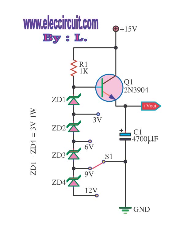
This is a DC regulator circuit that can provide multiple output voltages simply. It functions as a simple step-down DC converter and is designed with a fixed resistor R1. The described circuit operates as a DC voltage regulator, specifically designed...
Current-controlled switching-mode power supplies (SMPS) are increasingly popular due to their ability to allow pulse-by-pulse current control and monitoring, enhancing reliability and robustness compared to voltage-controlled alternatives. Current control also removes a positive zero in certain transfer functions, contributing...
It cannot be 0 volts, as the current does not flow freely due to the presence of the resistor. This results in one side being more negatively charged and the other side more positively charged, as electrons can move...
Most ATV (Amateur Television) transmitters use a DSB (Double Sideband) signal, while commercial television stations utilize a VSB (Vestigial Sideband) signal. This converter takes advantage of the lower sideband, leading to reduced interference from repeaters operating in the 440...
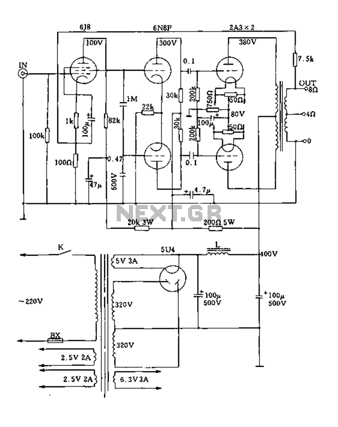
FIG. 2A3A is a low direct thermal resistance transistor with a resistance of only 800 ohms. The output transformer has a primary screen to load impedance of 3.5k ohms. The push-pull amplifier tube operates with a screen voltage ranging...
Warning: include(partials/cookie-banner.php): Failed to open stream: Permission denied in /var/www/html/nextgr/view-circuit.php on line 713
Warning: include(): Failed opening 'partials/cookie-banner.php' for inclusion (include_path='.:/usr/share/php') in /var/www/html/nextgr/view-circuit.php on line 713