
Pulse-amplitude-discriminator
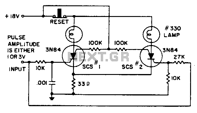
A 1-V amplitude pulse activates SCR1, but lacks sufficient amplitude to activate SCR2. A 3-V input pulse is delayed in reaching SCR1 due to the 10-KΩ and 0.001-µF integrating network. Instead, it activates SCR2, subsequently increasing the common emitter voltage to prevent SCR1 from being triggered. Additionally, the 100-KΩ resistors mitigate the rate effect.
The circuit involves a combination of silicon-controlled rectifiers (SCRs), resistors, and capacitors to control the triggering sequence and voltage levels. The first SCR, SCR1, is designed to be triggered by a low-amplitude pulse of 1 V. However, this pulse is insufficient to activate the second SCR, SCR2, which requires a higher voltage threshold for triggering.
The integration network, consisting of a 10-KΩ resistor and a 0.001-µF capacitor, introduces a delay in the signal reaching SCR1. This network effectively smooths out the input pulse, allowing a more gradual build-up of voltage across the capacitor. When a 3-V input pulse is applied, it successfully triggers SCR2 instead of SCR1. This is due to the increased voltage exceeding the threshold required for SCR2's activation.
Once SCR2 is activated, it raises the common emitter voltage in the circuit. This elevated voltage creates a condition that prevents SCR1 from being triggered, despite the presence of the initial 1-V pulse. The role of the 100-KΩ resistors is crucial in this setup, as they serve to suppress the rate effect, which can lead to unintended triggering of the SCRs. By controlling the rate of voltage change in the circuit, these resistors ensure that the SCRs operate reliably and as intended, maintaining the desired sequence of activation based on the input pulses.
This configuration illustrates a practical application of SCRs in electronic circuits, demonstrating how different voltage levels and timing can be manipulated to achieve specific outcomes in power control and switching applications.A 1-V amplitude pulse triggers SCSl, but has insufficient amplitude to trigger SCS2. A 3-V input pulse is delayed in reaching SCSl by the 10-KO and .001-!"F integrating network. Instead, it triggers SCS2, then raises the common emitter voltage to prevent SCSI from triggering. The 100-KO resistors suppress the rate effect. 🔗 External reference
Warning: include(partials/cookie-banner.php): Failed to open stream: Permission denied in /var/www/html/nextgr/view-circuit.php on line 713
Warning: include(): Failed opening 'partials/cookie-banner.php' for inclusion (include_path='.:/usr/share/php') in /var/www/html/nextgr/view-circuit.php on line 713