
PULSE PERIOD TO VOLTAGE CONVERTER
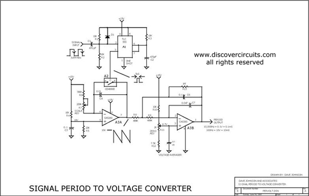
The circuit operates by using a timing mechanism that captures the duration of the square wave's high and low states. A monostable multivibrator can be employed to generate a pulse width that corresponds to the input signal's period. This pulse width is then fed into a voltage scaling circuit, which could be a resistor divider or an operational amplifier configured to amplify the voltage to the desired range.
The input square wave signal is connected to the trigger of the monostable multivibrator. When the signal transitions from low to high, the multivibrator generates a pulse whose width is determined by the time the input signal remains high. This pulse width is then converted into a proportional voltage using a resistive network or an op-amp circuit, which can be calibrated to output between 100mV and 10V based on the specified period range.
To ensure stability and accuracy, the circuit may include filtering components, such as capacitors, to smooth out any noise from the input signal. Proper selection of the multivibrator and voltage scaling components is crucial to achieve the desired performance characteristics. The use of a single 15V power supply simplifies the design and reduces the overall cost, making this circuit an efficient solution for applications requiring period measurement in various electronic systems.This is a test circuit converts a square wave input signal into a voltage. But, the voltage produced is proportional to the time between edges (period) of the signal, not the frequency. The range is from 100uS to to 10mS, which produces a voltage from 100mV to 10 volts. Other scale factors are also possible. The circuit is powered from single 15v supply and uses inexpensive parts. It is great when a signal`s period instead of its frequency needs to be monitored. Source: discovercircuits 🔗 External reference
Related Circuits
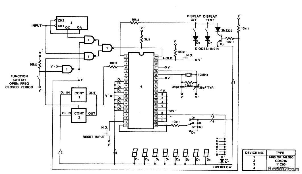
A 100 MHz frequency and period counter is constructed using the Intersil ICM7226B in a 40-pin DIP package. This circuit incorporates a CD4016 analog multiplexer to route the digital outputs back to the function input. The CD4016 operates as...
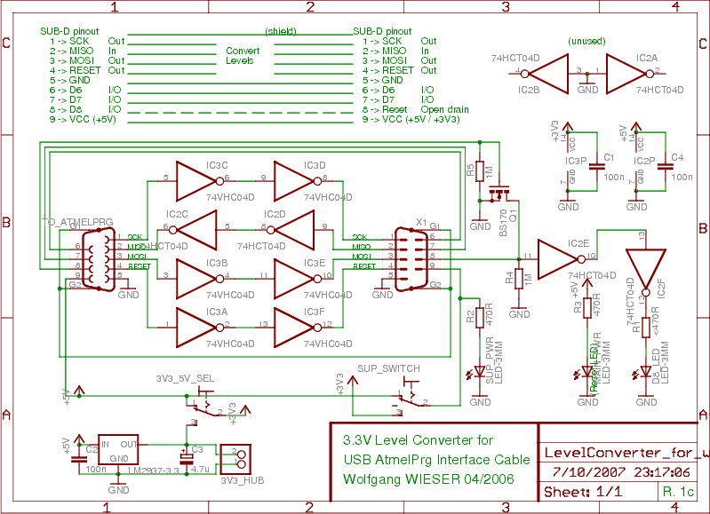
To program devices operating at 3.3V, such as SPI-based AVRs or JTAG-based CPLDs, level conversion is necessary for input and output signal levels. A 5V input may not register as HIGH at 3.3V, and a 3.3V device can be...

The circuit below demonstrates the generation of a single positive pulse that is delayed in relation to the trigger input time. It is similar to a previously described circuit but utilizes two stages, allowing for control over both the...

The LTC3113 fixed frequency buck-boost DC-DC converter can be utilized to design various power supply circuits that operate with input voltages that are above, below, or equal to the output voltage. The topology integrated into the IC ensures low...
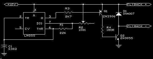
A 555 is used as an oscillator, optimally around 15.76KHz (in North America). Power pins on the chip (pin 1 to ground, pin 8 to +12V) are not shown on the diagram. The output from the 555 is then...
The first example utilizes a standard op-amp oscillator circuit to produce a triangular waveform, which is then level-shifted and supplied to a comparator (e.g., LM339) to generate a PWM waveform. It is common for users to prefer using two...