
Pulse-train-to-sinusoid-converter
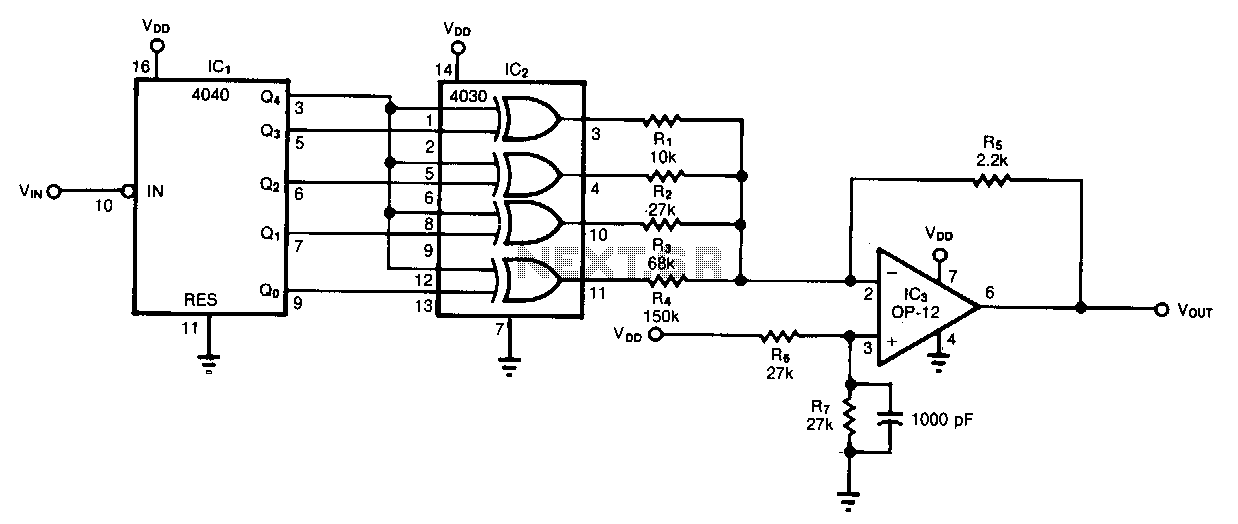
The circuit allows for the conversion of a serial pulse stream or sinusoidal input into a sinusoidal output at a frequency that is 1/32 of the input frequency. By adjusting the frequency of Vrn, an output frequency range of 107:1 can be achieved, spanning from approximately 100 kHz to less than 0.01 Hz. The output resembles that of a 5-bit digital-to-analog (D/A) converter operating on parallel digital data. Counter IC1 generates binary codes that continuously cycle through the range from 00000 to 11111. The output amplifier combines the corresponding outputs from the XOR gates, Vvv or ground, weighted according to the values of input resistors R1 through R4.
The 16 counter codes from 00000 to 01111 are passed unchanged to the outputs of the XOR gates, causing the output voltage (Vom) to progress through the half-sinusoidal cycle from maximum amplitude to minimum amplitude. When counter output Q4 goes high for the subsequent 16 codes, the XOR gates invert the outputs from Q0 through Q3. Consequently, the output voltage (VouT) transitions through the remaining half cycle from minimum to maximum amplitude. The counter then resets and begins the next cycle. The values of resistors R1 through R4 can be modified to generate different VouT waveforms. The voltage supply (VDv) should be at least 12 V to ensure maximum frequency operation from IC1 to IC2.
The circuit operates by employing a binary counter IC (IC1) that generates a sequence of binary codes. Each code corresponds to a specific state of the output waveform. The XOR gates play a crucial role in determining the output based on the current state of the counter. The selection of input resistors R1 through R4 directly influences the weighting of each output, allowing for a customizable output waveform that can be tailored to specific applications. The design is particularly effective for applications requiring precise frequency division and waveform shaping, making it suitable for signal processing tasks in various electronic systems.
To ensure optimal performance, maintaining a minimum supply voltage of 12 V is critical, as this facilitates the proper functioning of the counter and output stages. This circuit can be integrated into larger systems where frequency modulation or waveform generation is necessary, providing versatility in electronic design and implementation.The circuit letsyou convert a serial pulse stream or sinusoidal input to a sinusoidal output at 1/32 the frequency. By varying the frequency of Vrn, you can achieve an output range ofl07:1-from about 100 kH2 to less than 0.01 H2.
The output resembles that of a 5-bit d/a converter operating on paralleLdigital data. Counter IC1 generates binary codes that repeatedly scan the range from 00000 to 11111. The output amplifier adds the corresponding XOR gate outputs, Vvv or ground, weighted by the values of input resistors R1 through R4. The 16 counter codes 00000 to 01111, for instance, pass unchanged to the XOR gate outputs, and cause Vom to step through the half-sinusoidal cycle for maximum amplitude to minimum amplitude. Counter output Q4 becomes high for the next 16 codes, causing the XOR gates to invert the QO through Q3 outputs.
As a result, VouT steps through the remaining half cycle from minimum to maximum amplitude. The counter then rolls over and initiates the next cycle. You can change the R1 through R4 values to obtain other VouT waveforms. VDv should be at least 12 V to assure maximum-frequency operation from IC1 to IC2. 🔗 External reference