
Pulse-width-lamp-brightness-controller
At half brightness, the lamp current is pulsed on and off by the voltage developed across the resistor and capacitor at the current-sense output. The current-sense output detects the lamp current. A basic pulse-width modulation (PWM) lamp-brightness control circuit can also be constructed using this device. Upon powering up, the sense output is low, which pulls the comparator output and the on input low, thereby activating the FET switch. When the switch is activated, the current from the sense output charges the capacitor in the RC timing network to the 200 mV comparator threshold voltage. The comparator then triggers, turning the switch off. The charge on the capacitor subsequently leaks off, causing its voltage to drop below 100 mV, which turns the FET on again. The average current flowing through the load is primarily determined by the resistor value, while the pulse-width modulation frequency is influenced by the capacitor value.
The described circuit utilizes a pulse-width modulation technique to control the brightness of a lamp by varying the average current flowing through it. The operation begins with the current-sense output, which monitors the lamp current. At the initial state, the low voltage at the sense output activates the FET switch, allowing current to flow and charge the capacitor within the RC timing network. The charging process continues until the voltage across the capacitor reaches the predetermined threshold of 200 mV, at which point the comparator trips and deactivates the FET switch.
As the switch turns off, the capacitor begins to discharge, and its voltage decreases. When the voltage drops below 100 mV, the comparator resets, turning the FET switch back on, thereby restarting the cycle. This on-off pulsing of the lamp current results in an effective control of the brightness level, achieving a half-brightness state through rapid switching.
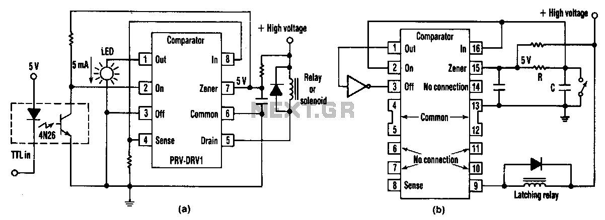
The average current through the lamp load is directly related to the resistance in the circuit; a higher resistance will result in lower average current and dimmer brightness, while a lower resistance will increase the average current and brightness. Conversely, the frequency of the pulse-width modulation is determined by the capacitance value in the timing network. A larger capacitor will slow the charging and discharging cycles, leading to a lower PWM frequency, while a smaller capacitor will allow for quicker cycles and a higher PWM frequency. This relationship between resistance and capacitance enables precise control over the lamp's brightness and is essential for applications requiring variable lighting conditions.At half brightness, the lamp current is pulsed on and off (Fig. 50-12b) by the voltage developed across the resistor and capacitor at the current-sense output. Lamp current is sensed by the current-sense output. A simple pulse-width modulation lamp-brightness control circuit can also be built with the device. When the device powers up, the sense output is low, pulling the comparator output and the on input low, and turning the FET switch on. When the switch is on, current from the sense output charges the capacitor in the rc timing network to the 200-mV comparator threshold voltage.
The comparator trips, turning the switch off. The charge then leaks off the capacitor, its voltage drops below 100 mV, and the FET is again turned on. The average current through the load is basically a function of the resistor value. The pulse-width modulation frequency on the other hand, is a function of the capacitor value. 🔗 External reference
The described circuit utilizes a pulse-width modulation technique to control the brightness of a lamp by varying the average current flowing through it. The operation begins with the current-sense output, which monitors the lamp current. At the initial state, the low voltage at the sense output activates the FET switch, allowing current to flow and charge the capacitor within the RC timing network. The charging process continues until the voltage across the capacitor reaches the predetermined threshold of 200 mV, at which point the comparator trips and deactivates the FET switch.
As the switch turns off, the capacitor begins to discharge, and its voltage decreases. When the voltage drops below 100 mV, the comparator resets, turning the FET switch back on, thereby restarting the cycle. This on-off pulsing of the lamp current results in an effective control of the brightness level, achieving a half-brightness state through rapid switching.
The average current through the lamp load is directly related to the resistance in the circuit; a higher resistance will result in lower average current and dimmer brightness, while a lower resistance will increase the average current and brightness. Conversely, the frequency of the pulse-width modulation is determined by the capacitance value in the timing network. A larger capacitor will slow the charging and discharging cycles, leading to a lower PWM frequency, while a smaller capacitor will allow for quicker cycles and a higher PWM frequency. This relationship between resistance and capacitance enables precise control over the lamp's brightness and is essential for applications requiring variable lighting conditions.At half brightness, the lamp current is pulsed on and off (Fig. 50-12b) by the voltage developed across the resistor and capacitor at the current-sense output. Lamp current is sensed by the current-sense output. A simple pulse-width modulation lamp-brightness control circuit can also be built with the device. When the device powers up, the sense output is low, pulling the comparator output and the on input low, and turning the FET switch on. When the switch is on, current from the sense output charges the capacitor in the rc timing network to the 200-mV comparator threshold voltage.
The comparator trips, turning the switch off. The charge then leaks off the capacitor, its voltage drops below 100 mV, and the FET is again turned on. The average current through the load is basically a function of the resistor value. The pulse-width modulation frequency on the other hand, is a function of the capacitor value. 🔗 External reference
Warning: include(partials/cookie-banner.php): Failed to open stream: Permission denied in /var/www/html/nextgr/view-circuit.php on line 713
Warning: include(): Failed opening 'partials/cookie-banner.php' for inclusion (include_path='.:/usr/share/php') in /var/www/html/nextgr/view-circuit.php on line 713