
Pulse-width-modulator
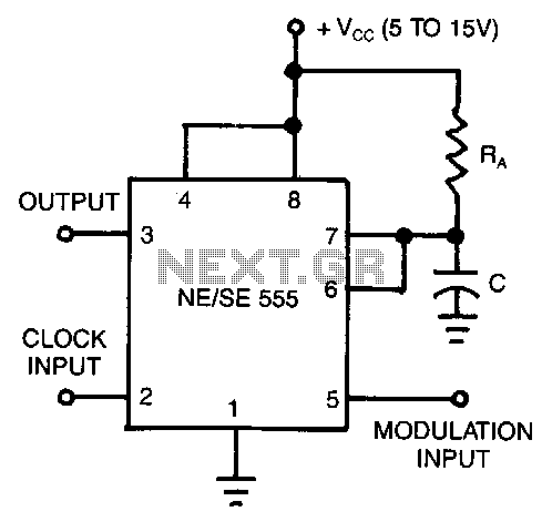
In this application, the timer operates in monostable mode. The circuit is activated by a continuous pulse train, and the threshold voltage is adjusted by the signal applied to the control voltage terminal at pin 5. This modulation of the control voltage results in a variation of the pulse width.
The circuit described utilizes a timer IC configured in monostable mode, which allows it to produce a single output pulse in response to an input trigger. In this configuration, the timer remains in a stable state until it receives a trigger signal. Upon receiving this trigger, the timer generates a pulse of a specific duration, which is determined by an external resistor-capacitor (RC) network connected to its timing pins.
The control voltage terminal at pin 5 plays a crucial role in this circuit by allowing for the modulation of the threshold voltage. When a varying control voltage is applied to this pin, it effectively alters the timing characteristics of the pulse generated. The relationship between the control voltage and the pulse width is such that an increase in control voltage typically leads to a decrease in pulse width, and vice versa. This feature enables dynamic control over the timing output, making the circuit highly versatile for various applications.
The waveform generated by this circuit, as illustrated in the accompanying figure, shows the relationship between the input pulse train and the output pulse. The output pulse width can be observed to change in accordance with the variations in the control voltage, demonstrating the effectiveness of this modulation technique in controlling timing parameters within electronic systems. This configuration is ideal for applications where precise timing adjustments are necessary, such as in signal processing or timing applications in digital circuits.In this application, the timer is connected in the monostable mode. The circuit is triggered with a continuous pulse train and the threshold voltage is modulated by the signal applied to the control voltage terminal at pin 5. This has the effect of modulating the pulse width as the control voltage varies. The figure shows the actual waveform generated with this circuit. 🔗 External reference