
-Pulse-width-multiplier
This circuit is designed to multiply the width of incoming pulses by a factor that can be either greater or less than one. It is straightforward to construct and features a single potentiometer for adjusting the multiplying factor. The multiplying factor is established by configuring the potentiometer in the feedback loop of a 741 operational amplifier. The input pulses, characterized by width T and repetition period T, are used to trigger a sawtooth generator at the rising edges, producing a waveform denoted as e2, which reaches a peak value of E volts. This peak value is then sampled by the input pulses to generate a pulse train referred to as e3, which has an average value of e4 (equal to E multiplied by r, where r is proportional to T and independent of T). The direct current (DC) voltage e4 is amplified by a factor k and compared with the sawtooth waveform e2, resulting in output pulses with a duration of kr. The circuit operates effectively within a frequency range of 10 kHz to 100 kHz. It is important to select k to be less than T/T to ensure precise pulse-width multiplication.
The circuit operates on the principle of pulse-width modulation and amplification using a 741 operational amplifier, which serves as the core component for feedback control. The input pulse width T is critical, as it dictates the timing and frequency of the output pulse train. The sawtooth generator is triggered by the rising edges of the input pulses, generating a triangular waveform that oscillates between 0 and E volts. The feedback loop, which includes the potentiometer, allows for real-time adjustments to the gain of the operational amplifier, thereby enabling fine-tuning of the multiplying factor.
The output pulse train e3 is generated by sampling the sawtooth waveform e2 at the specified intervals determined by the input pulses. The average value e4 is computed based on the peak value E and the ratio r, which is a function of T. This output is then amplified by the factor k, allowing for the adjustment of pulse duration in the final output. The relationship between the sawtooth waveform and the amplified DC voltage is fundamental, as it establishes the timing for the output pulses, which have a duration proportional to the product of k and r.
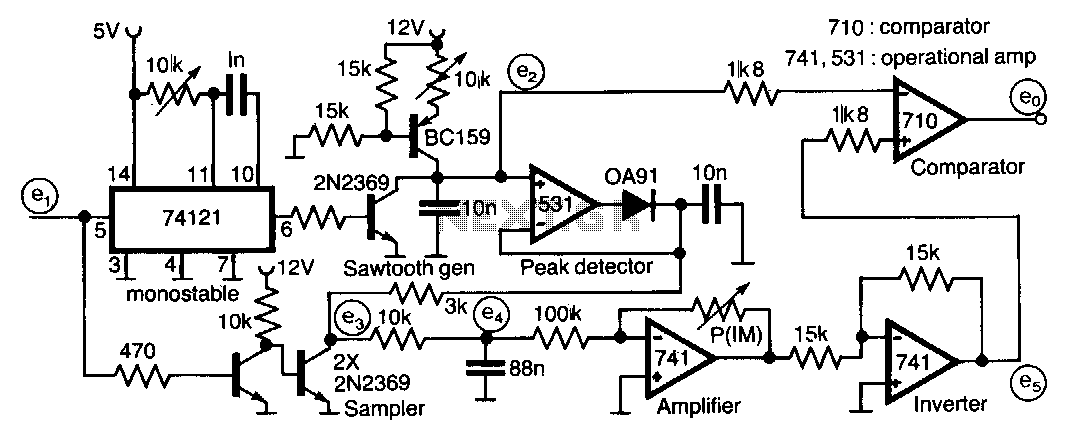
To maintain accuracy in pulse-width multiplication, careful consideration must be given to the selection of k. It is recommended that k remain less than the ratio of T to T to prevent distortion or inaccuracies in the output pulse widths. The circuit's frequency range of 10 kHz to 100 kHz indicates its versatility in various applications, including signal processing, communications, and other electronic systems where pulse-width modulation is utilized.This circuit for multiplying the width of incoming pulses by a factor greater or less than unity is simple to build and has the feature that the multiplying factor can be selected IYJ adjusting one potentiometer only. The multiplying factor is determined by setting the potentiometer in the feedback of the 741 amplifier.
The input pulses e1, width T and repetition period Tis used to trigger a sawtooth generator at its rising edges to produce the waveform e2 having a peak value of E volts. This peak value is then sampled by the input pulses~to generate the pulse train e3 having an average value of e4 ( = E rln which is proportional to T and independent on T. The de voltage e4 is amplified by a factor k and compared with sawtooth waveform e2 giving output pulses of duration kr.
The circuit is capable of operating over the frequency range 10 kHz-100kHz. Note that k should be chosen less than TIT to ensure accurate pulse-width multiplication. 🔗 External reference
The circuit operates on the principle of pulse-width modulation and amplification using a 741 operational amplifier, which serves as the core component for feedback control. The input pulse width T is critical, as it dictates the timing and frequency of the output pulse train. The sawtooth generator is triggered by the rising edges of the input pulses, generating a triangular waveform that oscillates between 0 and E volts. The feedback loop, which includes the potentiometer, allows for real-time adjustments to the gain of the operational amplifier, thereby enabling fine-tuning of the multiplying factor.
The output pulse train e3 is generated by sampling the sawtooth waveform e2 at the specified intervals determined by the input pulses. The average value e4 is computed based on the peak value E and the ratio r, which is a function of T. This output is then amplified by the factor k, allowing for the adjustment of pulse duration in the final output. The relationship between the sawtooth waveform and the amplified DC voltage is fundamental, as it establishes the timing for the output pulses, which have a duration proportional to the product of k and r.
To maintain accuracy in pulse-width multiplication, careful consideration must be given to the selection of k. It is recommended that k remain less than the ratio of T to T to prevent distortion or inaccuracies in the output pulse widths. The circuit's frequency range of 10 kHz to 100 kHz indicates its versatility in various applications, including signal processing, communications, and other electronic systems where pulse-width modulation is utilized.This circuit for multiplying the width of incoming pulses by a factor greater or less than unity is simple to build and has the feature that the multiplying factor can be selected IYJ adjusting one potentiometer only. The multiplying factor is determined by setting the potentiometer in the feedback of the 741 amplifier.
The input pulses e1, width T and repetition period Tis used to trigger a sawtooth generator at its rising edges to produce the waveform e2 having a peak value of E volts. This peak value is then sampled by the input pulses~to generate the pulse train e3 having an average value of e4 ( = E rln which is proportional to T and independent on T. The de voltage e4 is amplified by a factor k and compared with sawtooth waveform e2 giving output pulses of duration kr.
The circuit is capable of operating over the frequency range 10 kHz-100kHz. Note that k should be chosen less than TIT to ensure accurate pulse-width multiplication. 🔗 External reference