
push button relay selector

The circuit serves as a speaker selector that facilitates the connection of multiple speakers to a single stereo amplifier, allowing for easy comparison of audio performance across different speaker models. The design typically includes a rotary switch or a relay-based switching mechanism to select between various speaker outputs while ensuring that only one speaker pair is active at any given time.
Key components of the circuit may include a stereo amplifier input, a set of speaker outputs, a switching mechanism (such as a rotary switch or relays), and possibly indicator LEDs to show which speaker is currently selected. The circuit should be designed to handle the power ratings of the speakers and amplifier, ensuring that it can safely switch between them without introducing distortion or damaging components.
In addition to the basic functionality, the circuit may incorporate features such as impedance matching to prevent load issues, and protection circuits to safeguard the amplifier and speakers from overcurrent conditions. The layout should minimize interference and maintain signal integrity, with careful consideration given to wire lengths and grounding techniques.
Overall, this circuit is essential for audio enthusiasts and professionals who require an efficient and effective means to evaluate and demonstrate the audio characteristics of various speaker systems in a controlled environment.This circuit was designed for use in a hifi showroom, where a choice of speakers could be connected to a stereo amplifier for comparative purposes. It cou.. 🔗 External reference
Related Circuits
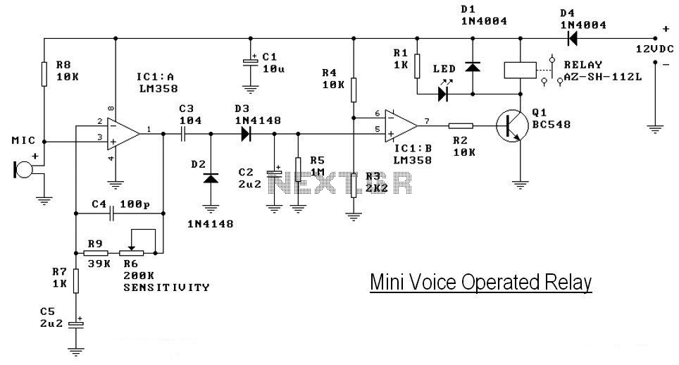
This circuit diagram represents a voice-operated relay. It functions similarly to a sound-activated switch circuit, which toggles the switch on and off (connects and disconnects) based on sound input. The output switch of this circuit is AC. The voice-operated relay...
High-end audio equipment is typically controlled digitally by a microprocessor (microcontroller) system. It is necessary to have a digital interface that allows for effective communication and control. High-end audio systems utilize a microcontroller to manage various functionalities, enabling precise control...
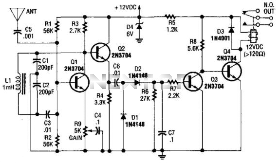
Q1 is used as an oscillator operating at approximately 300 kHz. Resistor R9 is configured to allow the oscillator to initiate its operation. An object near the antenna will load the circuit, causing the oscillations to cease. This change...
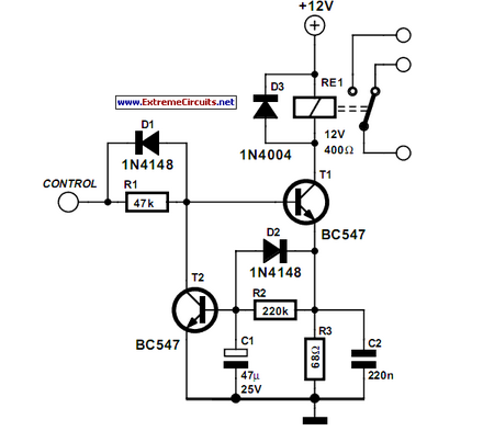
Some relays will become warm if they remain energized for some time. The circuit shown here will actuate the relay as before but then reduce the hold current. The described circuit addresses the issue of heat generation in relays due...
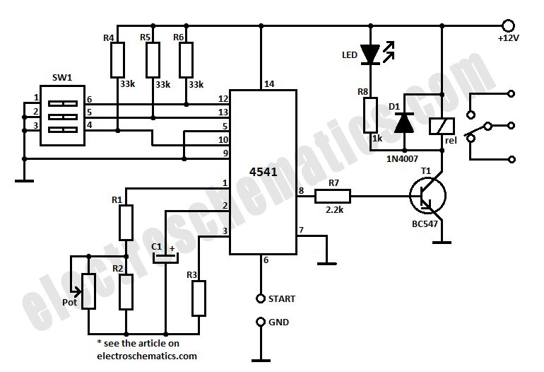
To initiate the timing process, there are two options available: either connect the START point to ground (GND), in which case the timer activates when connected to the voltage supply, or employ a switch to start the timer. The timing...
Circuit to close a relay when any phone extension is off-hook. Voltage at the gate of the MOSFET should be negative (1-3 volts) with respect to the source when phones are on-hook. Voltage at the gate should be positive...
Warning: include(partials/cookie-banner.php): Failed to open stream: Permission denied in /var/www/html/nextgr/view-circuit.php on line 713
Warning: include(): Failed opening 'partials/cookie-banner.php' for inclusion (include_path='.:/usr/share/php') in /var/www/html/nextgr/view-circuit.php on line 713