
PWM DC motor speed control circuit
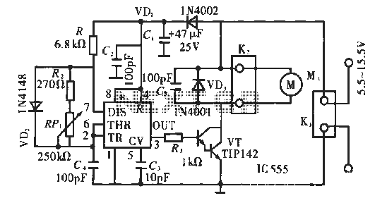
The circuit utilizes a 555 timer in astable mode, configured to generate a continuous square wave output. In this configuration, the output frequency and duty cycle are determined by the external resistors and capacitor connected to the timer. The fixed pulse width of 0.5 ms is achieved through careful selection of these components, allowing for precise control over the timing characteristics of the output signal.
The output from the 555 timer is fed into a transistor (VT), which acts as a switch to control the power delivered to the motor. When the output pulse from the 555 timer goes high, the transistor is turned on, allowing current to flow to the motor for the duration of the pulse. This brief activation is sufficient to start the motor, as it provides the necessary torque to overcome initial inertia.
In applications where pulse position modulation is preferred, this circuit design can offer advantages such as reduced electromagnetic interference and improved efficiency in motor control. The use of a fixed pulse width simplifies the design and can enhance reliability in various operating conditions. Additionally, further enhancements can be made by integrating feedback mechanisms to adjust the pulse frequency or width dynamically, allowing for more responsive motor control based on load conditions.
Overall, this circuit exemplifies a straightforward yet effective approach to motor control using pulse position modulation, leveraging the capabilities of the 555 timer and a transistor switch to achieve desired operational outcomes.Circuit works: At present, although the most commonly used method is to pulse width modulation speed, but the circuit is a pulse position modulation (when known as pulse modulation). Manifold 555 in here to pick a square wave modulator 3 feet output pulse width is fixed 0.5 ms (by the R., C. The time constant). Thus, the duration of each pulse through the VT the electric machine is turned on 0.5 ms. Most of this time is sufficient to start the motor.
Related Circuits
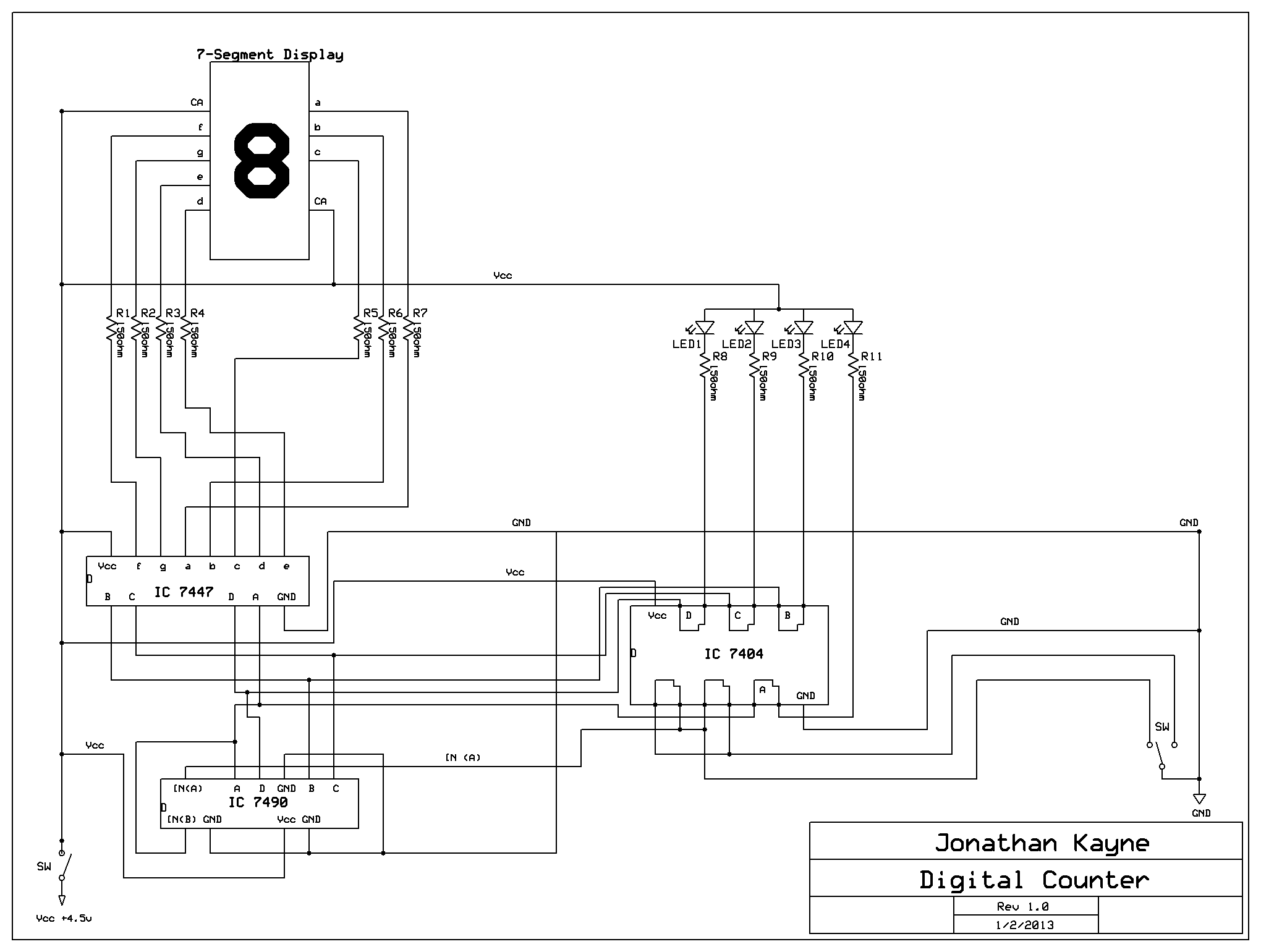
The Digital Counter Circuit is an electronic project that converts digital numbers (0-9) to binary (0-1). For those interested in understanding binary code, a PowerPoint presentation on the topic is available. Below are the parts list, schematic, and additional...
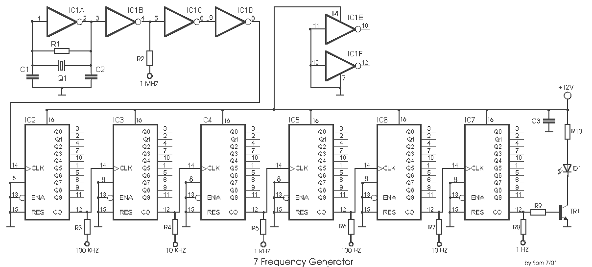
This is a useful instrument for workshops. The standard of the produced frequencies is 10 to 1. The basic frequency is produced by a crystal with high accuracy. The circuit consists of the oscillator, around the crystal and the...
Computers often experience overheating due to prolonged use or high ambient temperatures, making temperature controllers essential. Accurate temperature measurement is necessary to ensure that the computer operates within a safe temperature range. A circuit diagram for a simple temperature...
If a Squeezebox is present, it is likely accompanied by an amplifier. The inconvenience of manually turning the amplifier on and off, especially when the Squeezebox is stored in a cupboard, necessitates a device that automatically powers the amplifier...
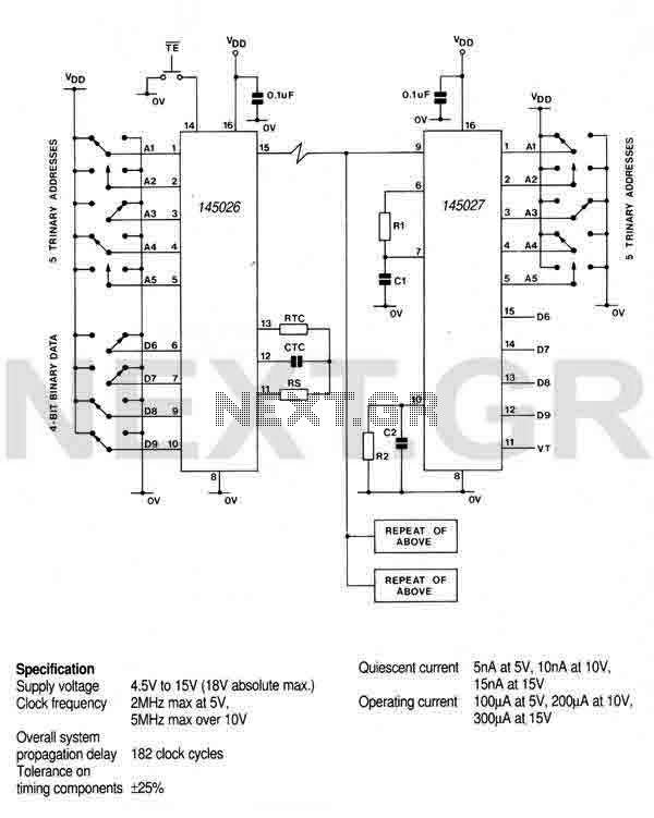
This encoder can generate up to 19,683 codes from 9 address lines by detecting 1, 0, or an open circuit. To initiate the transmit sequence, pin 14 should be pulsed low. The encoder will output a data stream on...
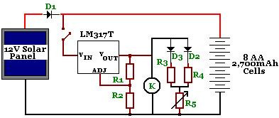
The circuit is designed to power a CCTV camera, provide lighting inside a nestbox, and charge batteries using a photovoltaic (PV) solar panel. It includes a circuit diagram for a solar-powered wireless CCTV camera with battery backup. D1 is...
Warning: include(partials/cookie-banner.php): Failed to open stream: Permission denied in /var/www/html/nextgr/view-circuit.php on line 713
Warning: include(): Failed opening 'partials/cookie-banner.php' for inclusion (include_path='.:/usr/share/php') in /var/www/html/nextgr/view-circuit.php on line 713