
PWM inverter circuit based on SG3524 : 12V input 220V output 250W
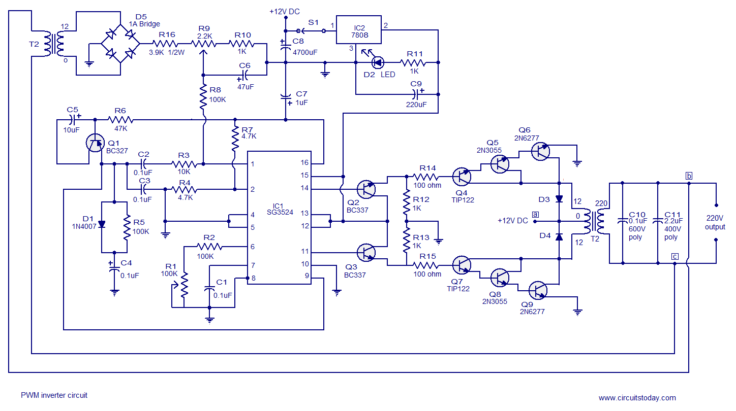
The described PWM inverter circuit employs the SG3524, a versatile PWM controller known for its efficiency in generating pulse-width modulation signals. The circuit operates with a 12V DC input, which is typically sourced from batteries or solar panels, making it suitable for off-grid applications or backup power systems.
The SG3524 is configured to generate a square wave output that drives a transformer, stepping up the voltage from 12V to 220V. The transformer is a crucial component, as it not only increases the voltage but also provides electrical isolation between the input and output, enhancing safety. The design can be adjusted to achieve a maximum output power of 250 watts, which is suitable for powering small appliances, lighting, or electronic devices.
To extend the output power beyond 250 watts, modifications can be made to the transformer and the switching components. This may include using a transformer with a higher power rating or paralleling multiple SG3524 circuits to share the load. Additionally, careful consideration must be given to heat dissipation and component ratings to ensure reliable operation under higher loads.
The circuit layout should include proper decoupling capacitors near the SG3524 to minimize noise and improve stability. Furthermore, incorporating feedback mechanisms can enhance the regulation of the output voltage, ensuring consistent performance under varying load conditions. Overall, this PWM inverter circuit presents a practical solution for converting low-voltage DC into high-voltage AC, with the flexibility to adapt to various power requirements.Simple PWM inverter circuit using SG3524. This PWM inverter circuit has 12V input, 220V output and 250 watt output power. Output power can be extended.. 🔗 External reference
Related Circuits
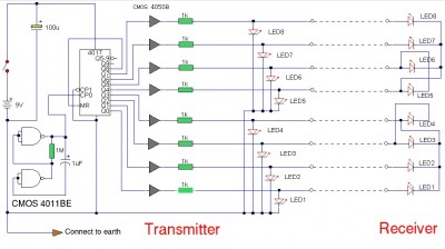
The LAN tester circuit can also test cables such as telephone, coaxial, LAN, and others. This circuit uses LEDs as the main indicator device. The LAN tester circuit is designed to verify the integrity and functionality of various types of...
The text of the Arduino reference is licensed under a Creative Commons Attribution-ShareAlike 3.0 License. Code samples in the reference are released into the public domain. The Arduino platform is an open-source electronics prototyping environment that enables users to create...
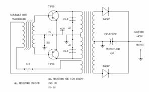
A car inverter, also known as a power converter or power inverter, is a device that converts 12V DC from a vehicle’s electrical system into 220V AC for general electrical use. It serves as a convenient power adapter for...
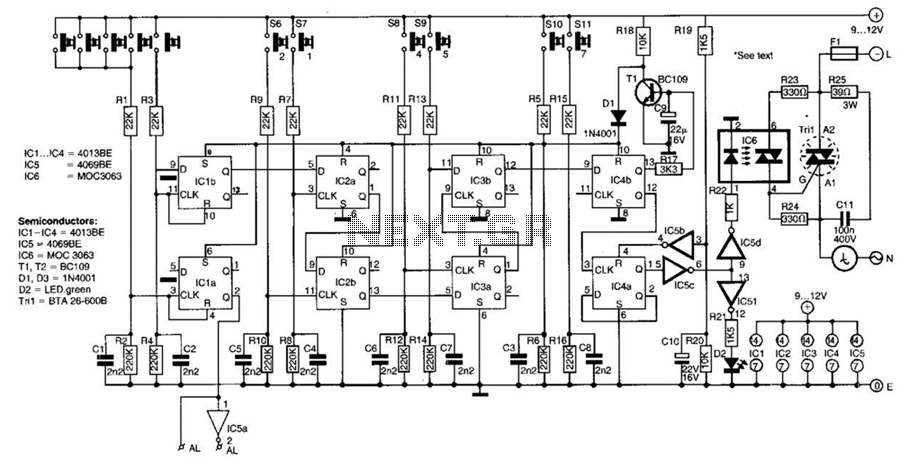
This switch utilizes four CD4013BE dual flip-flops, an inverter, and an optoisolator to control a triac, allowing it to switch a 25-A AC load current. A standard 4x3 telephone keypad is employed for entering a 6-digit code. In the...

The demonstration circuit operates in the HM2007's manual mode. This mode uses a simple keypad and digital display to communicate with and program the HM2007 chip. When the circuit is turned on, the HM2007 checks the static RAM. If...
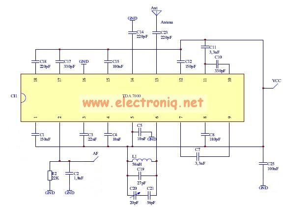
The TDA7000 features a Frequency-Locked-Loop (FLL) system with an intermediate frequency of 70 kHz, and selectivity is achieved through active RC filters. The only calibration required is for the resonant circuit associated with the oscillator, which is necessary for...
Warning: include(partials/cookie-banner.php): Failed to open stream: Permission denied in /var/www/html/nextgr/view-circuit.php on line 713
Warning: include(): Failed opening 'partials/cookie-banner.php' for inclusion (include_path='.:/usr/share/php') in /var/www/html/nextgr/view-circuit.php on line 713