
Pwm-motor-controller
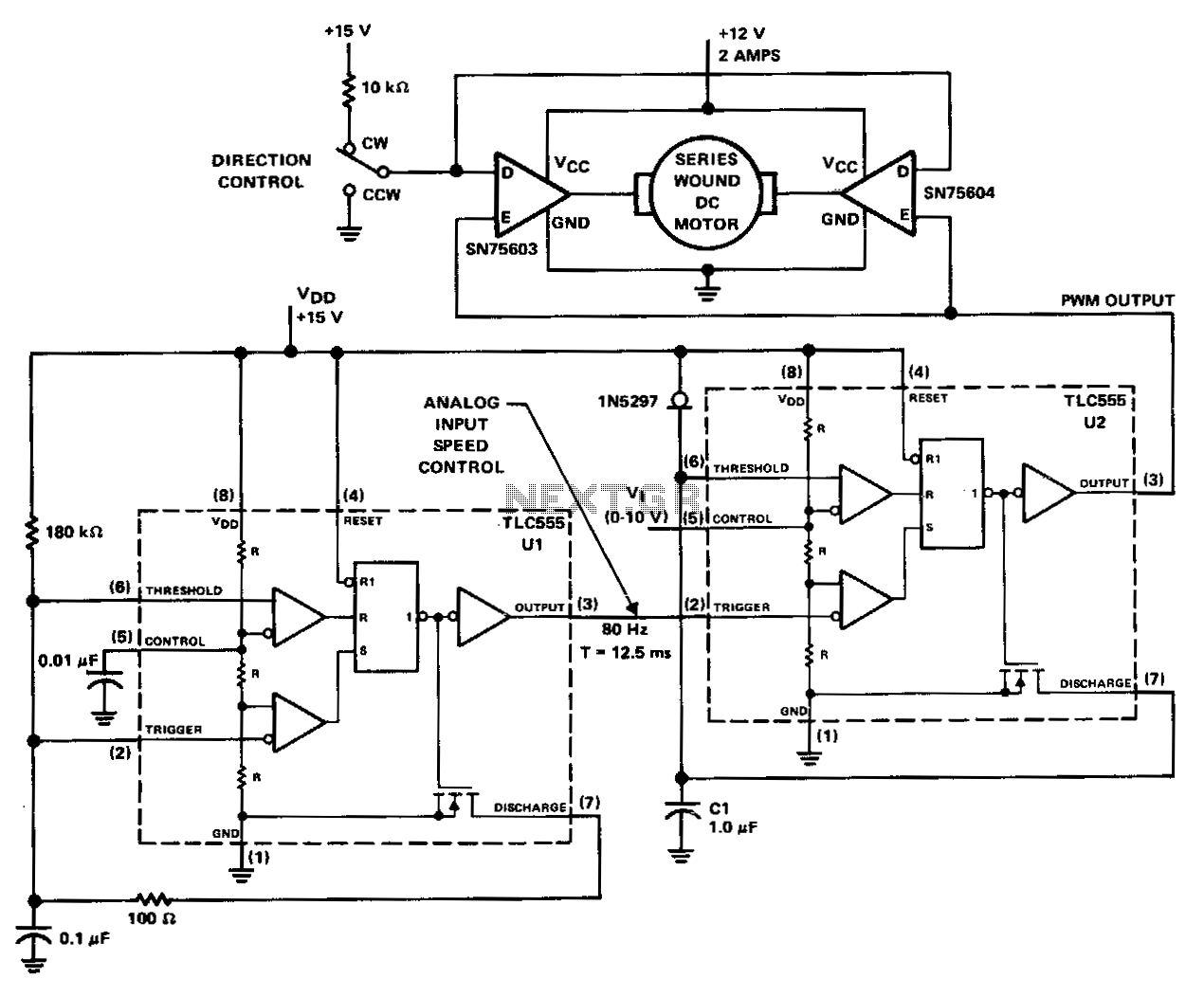
The PWM controller utilizes complementary half-H peripheral drivers SN75603 and SN75604, featuring totem-pole outputs rated at 40 V and 2.0 A. These drivers effectively configure the motor in a full-bridge setup, enabling bidirectional control. Timer U1 operates in astable mode at a frequency of 80 Hz. The 100-ohm discharge resistor results in an 8-microsecond trigger pulse, which is coupled to the trigger input of timer U2. Timer U2 functions as the PWM generator. Capacitor C1 is charged linearly with a constant current of 1 mA from the 1N5297, a FET current-regulator diode. Motor speed is controlled by supplying a DC voltage of 0 to 10 V to control input pin 5 of U2. As the control voltage increases, the width of the output pulse at pin 3 also increases. These pulses manage the on/off time of the two motor drivers. The trigger pulse width from timer U1 limits the minimum possible duty cycle from U2.
The PWM (Pulse Width Modulation) controller circuit is designed to provide effective motor control through a full-bridge configuration, utilizing the SN75603 and SN75604 drivers. This configuration allows for efficient bi-directional operation of the motor, making it suitable for applications requiring precise speed and direction control.
The core of the circuit is based on two timers, U1 and U2. Timer U1 is configured in astable mode, generating a continuous square wave signal at a frequency of 80 Hz. The output pulse from U1 is determined by the resistor-capacitor (RC) timing network, specifically a 100-ohm resistor that discharges to create an 8-microsecond pulse. This pulse is critical as it serves as a trigger for timer U2, which is responsible for generating the PWM signal.
Timer U2 operates as a PWM generator, where the duty cycle can be adjusted based on the control voltage applied to its input pin 5. The input voltage can range from 0 to 10 V, allowing for fine control over the motor speed. As the control voltage increases, the output pulse width from U2 at pin 3 also increases, effectively controlling the motor drivers' on and off states.
Capacitor C1 plays a significant role in this circuit by being charged linearly through a constant current of 1 mA supplied by the 1N5297 FET current-regulator diode. This linear charging ensures that the PWM signal can be modulated accurately, leading to a smooth and responsive motor speed adjustment.
Overall, this PWM controller design is effective for applications requiring precise motor control, with the ability to adjust speed and direction efficiently through a straightforward voltage control mechanism. The integration of the timers and the drivers ensures reliable operation and performance in various electronic motor control systems.The PWM controller uses complementary half-H peripheral drivers SN75603 and SN75604, with totem-pole outputs rated at 40 V and 2.0 A. These drivers effectively place the motor in a full-bridge configuration, which has the ability to provide bidirectional control.
Timer U1 operates in the astable mode at a frequency of 80Hz. The 100-0 discharge resistor results in an 8-p.s trigger pulse which is coupled to the trigger input of timer U2. Timer U2 serves as the PWM generator. Capacitor C1 is charged linearly with a constant current of 1 mA from the 1N5297, which is an FET current-regulator diode.
Motor speed is controlled by feeding a de voltage of 0 to 10 V to control input pin 5 of U2. As the control voltage increases, the width of the output pulse pin 3 also increases. These pulses controLthe on/ off time of the two motor drivers. The trigger pulse width of timer U1 limits the minimum possible duty cycle from U2. 🔗 External reference