
PWM tutoria
PWM (Pulse Width Modulation) circuits are widely utilized in various applications due to their efficiency and simplicity in controlling power delivery. The fundamental principle behind PWM involves switching a digital signal on and off at a high frequency, thereby varying the duty cycle, which is the ratio of the on-time to the total time of the signal cycle. By adjusting the duty cycle, the average power delivered to a load can be controlled effectively.
In LED dimming applications, PWM allows for smooth brightness control without the color distortion that can occur with resistive dimming methods. For instance, a microcontroller can generate a PWM signal that modulates the brightness of an LED by turning it on and off rapidly. The perceived brightness will vary depending on the duty cycle; a higher duty cycle results in brighter illumination.
In motor control, PWM can be employed to adjust the speed of DC motors. By varying the duty cycle of the PWM signal sent to the motor driver, the effective voltage and current supplied to the motor can be controlled, thus regulating its speed. This method is particularly advantageous as it minimizes energy loss compared to using resistors or variable resistors.
For thermoelectric coolers (TECs), PWM control enables precise temperature regulation by modulating the power supplied to the device. This is crucial in applications requiring temperature stability, such as in cooling electronic components or maintaining specific temperatures in laboratory settings.
When designing PWM circuits, it is important to consider the maximum voltage and current ratings of the components involved to prevent damage. Additionally, filtering may be required to smooth out the PWM signal when driving certain loads, especially inductive loads like motors. This can be achieved using capacitors or inductors to create low-pass filters that reduce voltage ripple and provide a more stable output.
Overall, PWM circuits offer a robust solution for power management in various electronic applications, making them a fundamental topic in electronics engineering.PWM circuits are fun. You can use them to dim LEDs, control the speed of fans and motors, control the power going to a thermoelectric cooler, or control the power going to pretty much anything you want. Just make sure that you don`t exceed the maximum voltage rating of your device. The video explains it all. 🔗 External reference
Related Circuits
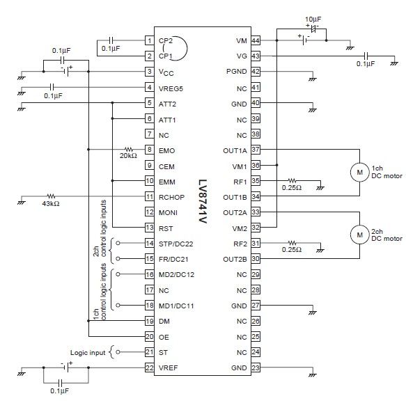
The circuit diagram illustrates an electronic project that requires a few external electronic components. The PWM current-control stepping motor driver IC can provide a maximum output current of up to 1.5 amperes. The configuration settings for the PWM current-control...
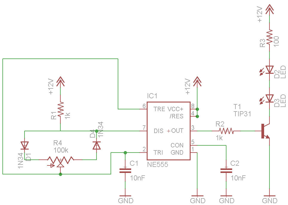
PWM waveforms are frequently employed to regulate the speed of DC motors. The mark/space ratio of the digital waveform can be established either by utilizing an adjustable analog voltage level (as seen in a NE555-based PWM generator) or through...
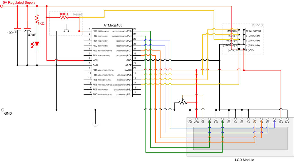
EEPROM (Electrically Erasable Programmable Read-Only Memory) is non-volatile memory, meaning it retains data even after power is removed. The ATmega168 microcontroller includes 512 bytes of EEPROM, which can be utilized to store system parameters and small amounts of data....
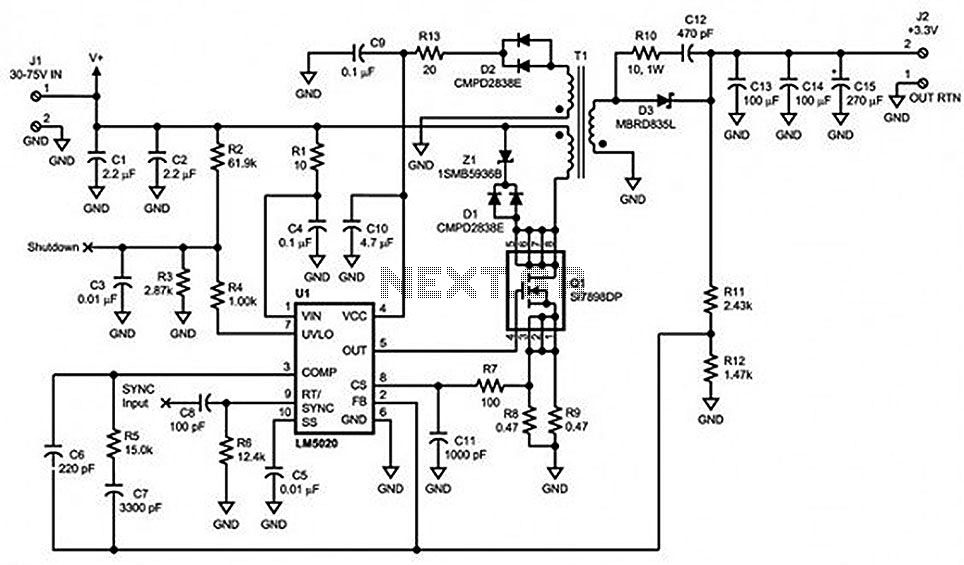
Locate sections such as the LM5020 connection diagram and pin descriptions, the functional block diagram of the device, the line under voltage lockout (UVLO) circuit, an internal high-gain error amplifier, a cycle-by-cycle overcurrent protection function, the setting of the...
This circuit serves as an introduction to pulse-width modulation experimentation, utilizing a dual 555 timer for simplicity. A small PCB has been designed to facilitate construction. Although not an original design, it complements the "Dimmer with MOSFET" article on...
PWM rectifier power controller power supply. Visit the page to read the explanation about the associated circuit diagram. A PWM (Pulse Width Modulation) rectifier power controller is a sophisticated electronic circuit designed to convert alternating current (AC) to direct current...