
pwm using 555 timer ic
The 555 timer in monostable mode functions effectively for generating precise timing pulses. The circuit configuration typically includes a resistor (R2) and a capacitor (C2) connected to the discharge pin (pin 7) of the IC. When the trigger signal is applied, the capacitor charges through the resistor, leading to a voltage increase across C2. The time constant for this charging process is influenced by both the resistance and capacitance values, allowing for flexibility in pulse width adjustment.
The differentiator circuit, which is crucial for providing sharp trigger pulses, typically consists of a resistor and capacitor arranged to form a high-pass filter. This configuration ensures that only rapid changes in the input signal are detected as triggers, thus enhancing the responsiveness of the 555 timer. The diode in the circuit plays a vital role in protecting the timer from unintended voltage spikes that could disrupt normal operation.
The control pin (pin 5) allows for further modulation of the output pulse width by applying a varying voltage. This feature is particularly useful in applications requiring dynamic pulse width adjustment, such as in motor speed control or PWM (Pulse Width Modulation) for LED brightness control. The behavior of the output signal can be tailored by selecting appropriate values for R2 and C2, as well as by varying the control voltage.
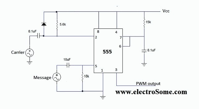
In summary, the 555 timer in monostable mode is a versatile component that can be employed in various electronic applications. Its ability to generate stable timing pulses, alongside the modulation capability provided by the control pin, makes it suitable for tasks ranging from simple timing applications to more complex control systems in robotics and automation.The 555 IC is wiredin monostable mode of operation. Please read the article Monostable Multivibrator using 555 Timer for more details. In this mode the output is LOW (0V) when there is no triggering, when it istriggeredvia 2nd pin the output goes HIGH (Vcc) for some time. This time period is determinedby the expression T=1. 11 RC (R=R2 ; C=C2 in the diagram). Trigger is applied via a differentiator circuit to make sharp pulses. The resistor of differentiator is connected to Vcc to generate negative trigger pulses and the diode avoids positive spikes. And now this outputis modulated using the input voltage applied at the control pin of the IC. So whenever the trigger pin pulses become low, the output of the IC switches to high and as a result the discharge transistor (internal to the 555 IC attached to the 7th pin) is disabled.
So C2 charges through R2. This capacitor keeps on charging until the voltageis above the input control voltage, at which the IC changes its state. Now the output is low which makes the discharge transistor activated thereby discharging the capacitor C2.
Hence the output pulse width is determined by the control voltage. This process continues and we get a continuousstream of pulses which can be used for motor control, driving LED`s, transmittingservo signals for remote control applications etc. 🔗 External reference
Related Circuits
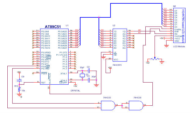
In the circuit presented, the LCD module's Command Register is configured at address 00H and the Data Register at address 01H. Consequently, writing data to address 00H will be interpreted as a command for the LCD, while writing to...

This design features a simple yet effective receiver with good sensitivity and selectivity. The circuit utilizes a compact three-transistor regenerative receiver with fixed feedback, primarily based on the BC549 transistor. The tuned circuit is intended for medium wave frequencies...
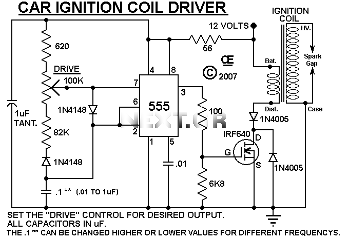
A simple design based on a 555 to drive a car ignition coil. This was designed for a small electric fence to protect a vegetable garden from small animals called marmots. Last year, they ate one of the crops...

The objective of the circuit is to create an electronic dice using the functionality of a 555 timer integrated circuit operating in astable mode. The electronic dice circuit utilizes a 555 timer configured in astable mode to generate a series...
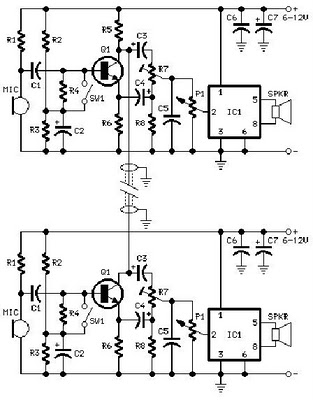
A project is proposed to construct a two-phone intercom system capable of functioning over a distance of up to 1 kilometer. The system will utilize the speaker of each phone to produce a ringing sound on the other end. The...
The iPod Shuffle has malfunctioned, likely due to a failure in the controller chip for the mini jack, resulting in the inability to detect the charger, PC connection, or headphones. The arc must be kept short to minimize distortions...
Warning: include(partials/cookie-banner.php): Failed to open stream: Permission denied in /var/www/html/nextgr/view-circuit.php on line 713
Warning: include(): Failed opening 'partials/cookie-banner.php' for inclusion (include_path='.:/usr/share/php') in /var/www/html/nextgr/view-circuit.php on line 713