
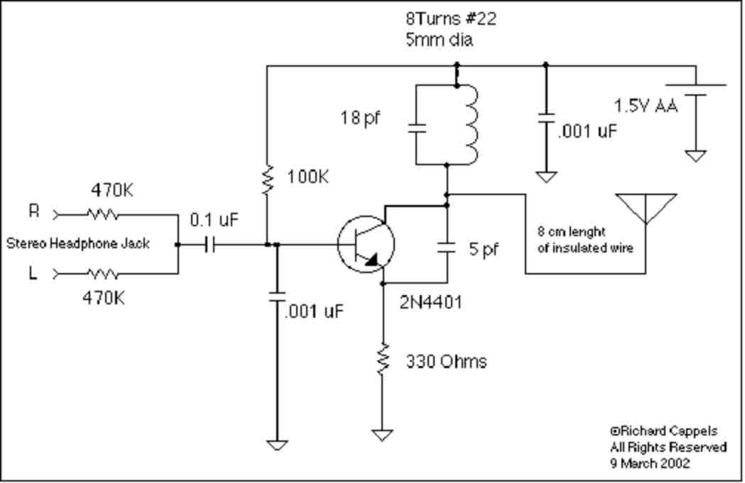
pyro rf transmitter 27mhz
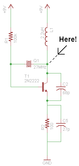
The pyro RF transmitter circuit comprises several key components that work in concert to generate and transmit signals effectively. The first stage involves the crystal oscillator, which is crucial for establishing a stable frequency output. The oscillator typically employs a quartz crystal that resonates at a precise frequency when an AC voltage is applied. This resonance produces a sine wave signal, which is essential for the RF transmission. Although harmonics are present due to the lack of filtering, they can often be tolerated in practical applications, provided that the fundamental frequency remains intact.
Next, the circuit incorporates a 555 timer configured in astable mode, generating a square wave signal at a lower frequency. This square wave serves as a digital on/off control signal that modulates the amplitude of the sine wave generated by the oscillator. The output of the 555 timer is characterized by sharp transitions between high and low states, making it suitable for digital applications where precise timing is critical.
The combination of the sine wave and the square wave occurs in the mixing stage of the circuit. This stage is designed to modulate the RF signal with the digital control signal, effectively encoding the information to be transmitted. The mixing process can be accomplished using a variety of methods, including analog multipliers or diode mixers, depending on the desired outcome and complexity of the circuit.
Finally, the power output stage of the transmitter amplifies the modulated signal to a suitable level for transmission. This stage may include RF amplifiers that boost the signal strength while maintaining the integrity of the modulation. Measurements taken at this stage provide insights into the efficiency and performance of the transmitter, including power output levels and signal quality.
In conclusion, the pyro RF transmitter circuit is a nuanced assembly of components that work together to generate, modulate, and transmit signals. Understanding the function of each component and the interactions between them is crucial for designing effective RF transmission systems.Instead of focusing on the mathematical and raw theoretical side of this simple pyro RF transmitter, we`ll be focusing on the elements in each of the stages. The math of how/why this circuit actually works is horridly ugly and way too complicated. so it`s funner (for me) to just build and get a `feeling` for what works and why and where and how. So let`s take some time to go through the schematic step by step to understand each part of the circuit, what it`s purpose is and what the signals look like at specific important points. We will go through 3 sections, first taking a look at how the signals we want to transmit are generated, then moving on to see how those signals look when we finally want to transmit them and then finally we`ll look at some measurements of the power output of the transmitter.
Before we can do anything for this transmitter, we need to generate the signals that we`ll be transmitting. So first, looking back at the schematic, here is the part of the circuit that gets the crystal oscillator going: Above you can see that the circuit outputs a sin-wave at the frequency we`re looking for.
Because there is no filtering many harmonic frequencies are present that skew our results slightly, but this signal will work. The next signal that we want to generate is the lower frequency on/off `digital` signal. We use a simple 555 timer to do that with the configuration seen below: The output is a solid square wave, just as we would expect to see.
Now, let`s see what happens when these two signals are mixed together! 🔗 External reference
Related Circuits
This transmitter can be powered by a 9V battery (not exceeding 12V). Users can connect a music source at the microphone input or utilize a simple condenser microphone. The signal range can reach up to 400 meters in open...
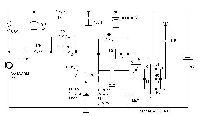
The RF oscillator utilizes inverter N2 and a 10.7 MHz ceramic filter to drive the parallel combination of inverters N4 to N6 through inverter N3. Since these inverters are connected in parallel, the output impedance is low, allowing direct...

The tuned coil L1 has two output tap points for the antenna connection, labeled "A" and "B." Both outputs are low-level, allowing the user to select between a stable low range or a more unstable but higher range. Tap...
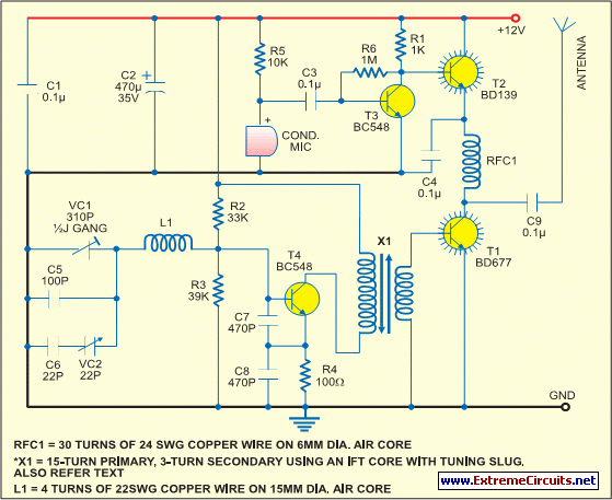
This low-cost short-wave transmitter is tunable from 10 to 15 MHz using a ½J gang condenser (VC1), which determines the carrier frequency in conjunction with inductor L1. Frequency trimming is achieved with VC2. The carrier signal is amplified by...
This implementation is adapted to rebroadcast the output of a CD player, television receiver, or radio receiver. I use it so that I can move about the house and listen to my favorite programs without disturbing others. Within the...
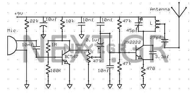
The moderate power FM transmitter circuit employs two transistors. The voice signals picked up by the microphone will be amplified by the transistor. The described FM transmitter circuit utilizes two transistors to facilitate the modulation and amplification of audio signals....