
Qrp-cw-transceiver
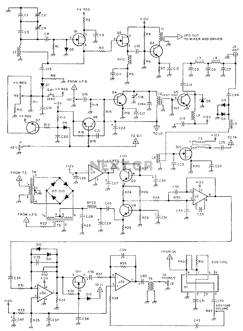
This is a 3-W, single-circuit board, VFO-controlled CW transceiver for 40 or 30 meters, featuring a direct-conversion receiver with audio filtering, Receiver Incremental Tuning (RIT), and speaker-level audio volume. The transmit frequency is generated by Q1 and its associated components in the VFO. The buffer, Q2, isolates the oscillator from the other circuitry to help keep the VFO stable. Q3 builds up the signal to a more usable level. The driver, Q4, amplifies the signal. The final stage, Q5, amplifies it to the 3-W level. Key the transmitter by turning the power to the driver on and off, using Q6 as a switching transistor. Select the frequency by varying the tuning capacitor, C2. The VFO frequency feeds into the diode-ring mixer and is mixed with the incoming 7- or 10-MHz signal. The difference, or product, is the audio frequency. The post-mixer circuitry amplifies the audio signal to speaker level: Q8 preamplifies the signal slightly, U2 is an audio filter that attenuates the audio signals above about 700 Hz, and U3 amplifies the signal from the audio filter to listening level.
The VFO-controlled CW transceiver operates on 40 or 30 meters, providing a compact and efficient solution for amateur radio communication. The core of the transmitter is based on a single-circuit board design, which minimizes space and enhances reliability. The direct-conversion receiver architecture simplifies the signal processing by directly converting the RF signal to audio frequency, allowing for effective reception of CW signals.
In this transceiver, the variable frequency oscillator (VFO) generates the transmit frequency through Q1 and its related components. This oscillator is crucial for maintaining frequency stability, which is achieved through the isolation provided by Q2. This buffer stage prevents loading effects from subsequent stages, ensuring that the oscillator remains stable under varying conditions.
The signal amplification process is divided into several stages. Q3 serves as a signal booster, preparing the signal for further amplification. The driver stage, implemented with Q4, significantly increases the signal strength before it reaches the final amplification stage, Q5, which is responsible for delivering the output power of 3 W. This multi-stage amplification ensures that the transceiver can effectively communicate over the desired frequency bands.
Frequency selection is accomplished by adjusting the tuning capacitor, C2, allowing the operator to fine-tune the transceiver to the desired frequency. The VFO output is then fed into a diode-ring mixer, where it is combined with an incoming 7- or 10-MHz signal. The mixing process produces an audio frequency, which is crucial for CW operation.
Post-mixer processing includes a series of amplification and filtering stages. Q8 acts as a preamplifier, providing an initial boost to the audio signal. Following this, U2 functions as an audio filter, designed to attenuate frequencies above approximately 700 Hz, thereby reducing noise and enhancing the clarity of the CW signal. The final amplification stage, U3, raises the filtered audio signal to an appropriate level for speaker output, ensuring that the operator can clearly hear the transmitted signals.
Overall, this VFO-controlled CW transceiver presents a well-engineered solution for amateur radio enthusiasts, combining essential features with efficient circuit design to facilitate reliable communication on the 40 and 30-meter bands.This is a 3-W, single-circuit board, VFO-controlled CW transceiver for 40 or 30 meters, featuring a direct-conversion receiver with audio filtering, Receiver Incremental Tuning (RIT), and speaker level audio volume. The transmit frequency is generated by Ql and its associated components in tbe VFO. The buffer, Q2, isolates the oscillator from the other circuitry to help keep the VFO stable. Q3 builds up tbe signal to a more usable level. The driver, Q4, amplifies the signal. The final, Q5, amplifies it to the 3-W level. Key tbe transmitter by turning the power to tbe driver on and off, using Q6 as a switching transistor. Select tbe frequency by varying tbe tuning capacitor, C2. The VFO frequency feeds into the diode-ring mixer, and is mixed with the incoming 7-or 10-MHz signal.
The difference, or produce, is the audio frequency. The post-mixer circuitry amplifies tbe audio signal to speaker level: Q8 preamplifies the signal a little, U2 is an audio filter tbat attenuates the audio signals above about 700Hz, and U3 amplifies tbe signal from the audio filter to listening level. 🔗 External reference