
Qrp-swr-bridge
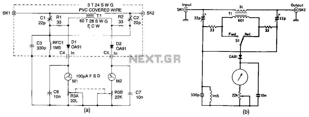
The design presented is a straightforward unit intended for QRP (low-power) operation across all authorized frequencies up to 30 MHz. It utilizes a toroidal transformer (T1). The secondary winding of T1 captures a small portion of RF power, both forward and reflected. This power is processed through a bridge circuit and rectified by diodes D1 and D2. Simultaneous readings of forward and reflected power are displayed on two meters (M1 and M2), while the bridge is matched and balanced to the desired load impedance using capacitors C1 and C2. An alternative, more cost-effective single meter version can be referenced in Fig. 56-9b. The bridge also measures forward power.
The QRP power measurement unit is designed to operate efficiently within the amateur radio spectrum, specifically up to 30 MHz. The core component, a toroidal transformer (T1), serves as a critical element in sampling RF power levels. The secondary winding of T1 is engineered to extract a small fraction of both forward and reflected RF power, which is essential for assessing the performance of RF amplifiers and antennas.
The bridge circuit plays a vital role in the functionality of this design, enabling the simultaneous measurement of both forward and reflected power. The rectification process is achieved through the use of diodes D1 and D2, which convert the AC signals from the bridge into DC voltage levels that can be read by the meters. Meters M1 and M2 are calibrated to provide direct readings of forward and reflected power, respectively, allowing the operator to monitor the efficiency of the transmission system in real-time.
To ensure accurate measurements, the bridge circuit must be matched and balanced to the load impedance, which is accomplished through the adjustable capacitors C1 and C2. These capacitors allow for fine-tuning of the circuit to achieve optimal performance, thereby ensuring that the readings on the meters are reliable.
For those seeking a more economical solution, an alternative configuration is available, which utilizes a single meter for power measurement. This version is detailed in Fig. 56-9b, providing a simplified approach while still maintaining essential functionality. The ability to measure forward power is particularly advantageous for operators aiming to optimize their QRP setups, as it provides critical feedback on power levels being transmitted. Overall, this design represents a practical solution for amateur radio enthusiasts engaged in low-power operations, emphasizing both accuracy and efficiency in power measurement.The design shown is a simple unit for QRP operation on all authorized frequencies up to 30 MHz. based on a toroidal transformer Tl. The secondary winding of Tl samples a small amount o1 rf power. both forward and reflected, which is divided by the bridge circuit and rectified by diodes Dl and D2. Forward and reflected readings are obtained simultaneously on the two meters Ml and M2, and the bridge is matched and balanced at the required load impedance by Cl and C2.
See Fig. 56-9b for an alternative, less expensive, single meter version. The bridge also measure forward power. 🔗 External reference