
Quadruple semi-continuous casting machine speed control circuit
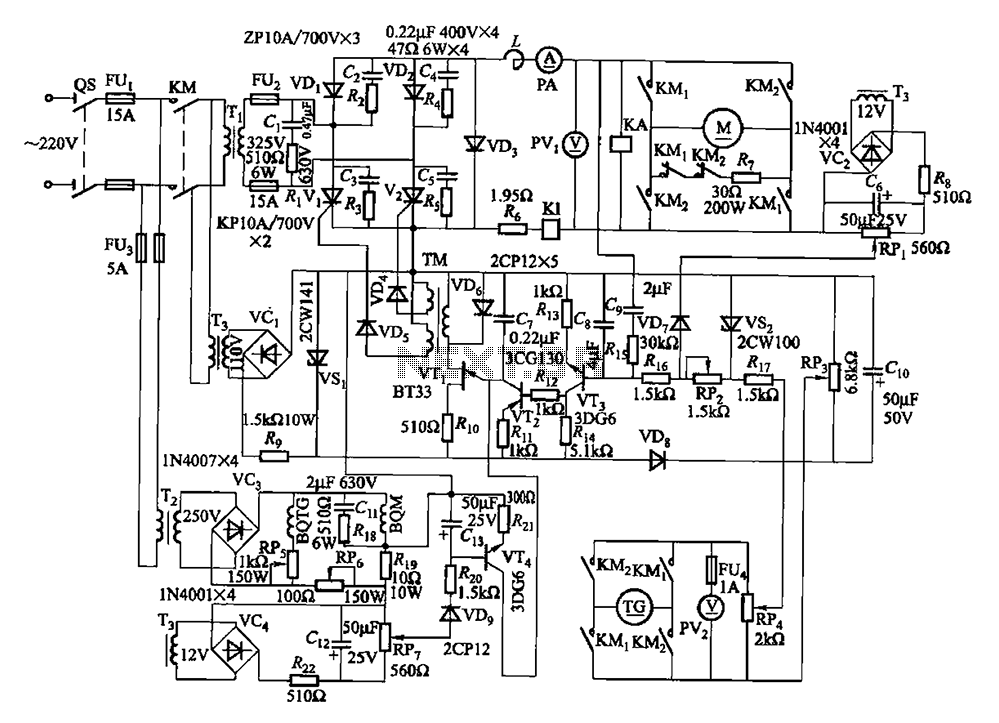
The described circuit operates within the framework of a simple yet effective control system for a DC motor. The main circuit integrates various components to ensure optimal performance and protection of the motor. The trigger circuit is responsible for initiating the operation of the motor by providing the necessary starting signal.
The speed negative feedback mechanism plays a crucial role in maintaining the desired operational speed of the motor. It continuously monitors the motor speed and adjusts the excitation voltage accordingly to compensate for any deviations from the set speed. This feedback loop enhances the stability of the system.
The negative feedback differential voltage circuit further refines the control by comparing the actual speed of the motor with the desired speed, allowing for precise adjustments. The current cut-off circuit is a safety feature that disconnects the motor in the event of an overload, preventing potential damage.
Additionally, the loss of field protection circuit is implemented to safeguard against situations where the field winding loses its excitation, which can lead to unstable motor operation. The use of a single-phase circuit is appropriate for the low power rating of the motor, simplifying the design and reducing costs.
The variable transformer Tz, in conjunction with the rectifier bridge, converts the AC input voltage into a suitable DC voltage, VC3, which serves as the excitation voltage for the motor and tachometer generator. The master adjust potentiometer RP3 provides an interface for operators to manually adjust the motor speed, enabling flexibility in various applications where speed control is necessary.
Overall, this circuit design incorporates multiple safety and control features to ensure reliable operation of the DC motor while allowing for user-adjustable speed settings. Circuit from the main circuit, trigger circuit, speed negative feedback, negative feedback differential voltage, current cut-off circuit, loss of field protection and other com ponents. Since the motor power is small (1. lkW), so the use of single-phase circuits. Figure, BQM and BQTG are DC motor M and the tachometer generator TG field winding. They consist of variable Tz by the rectifier bridge voltage VC3 offers the exciting voltage. Master adjust potentiometer RP3, can change the motor speed.
Related Circuits
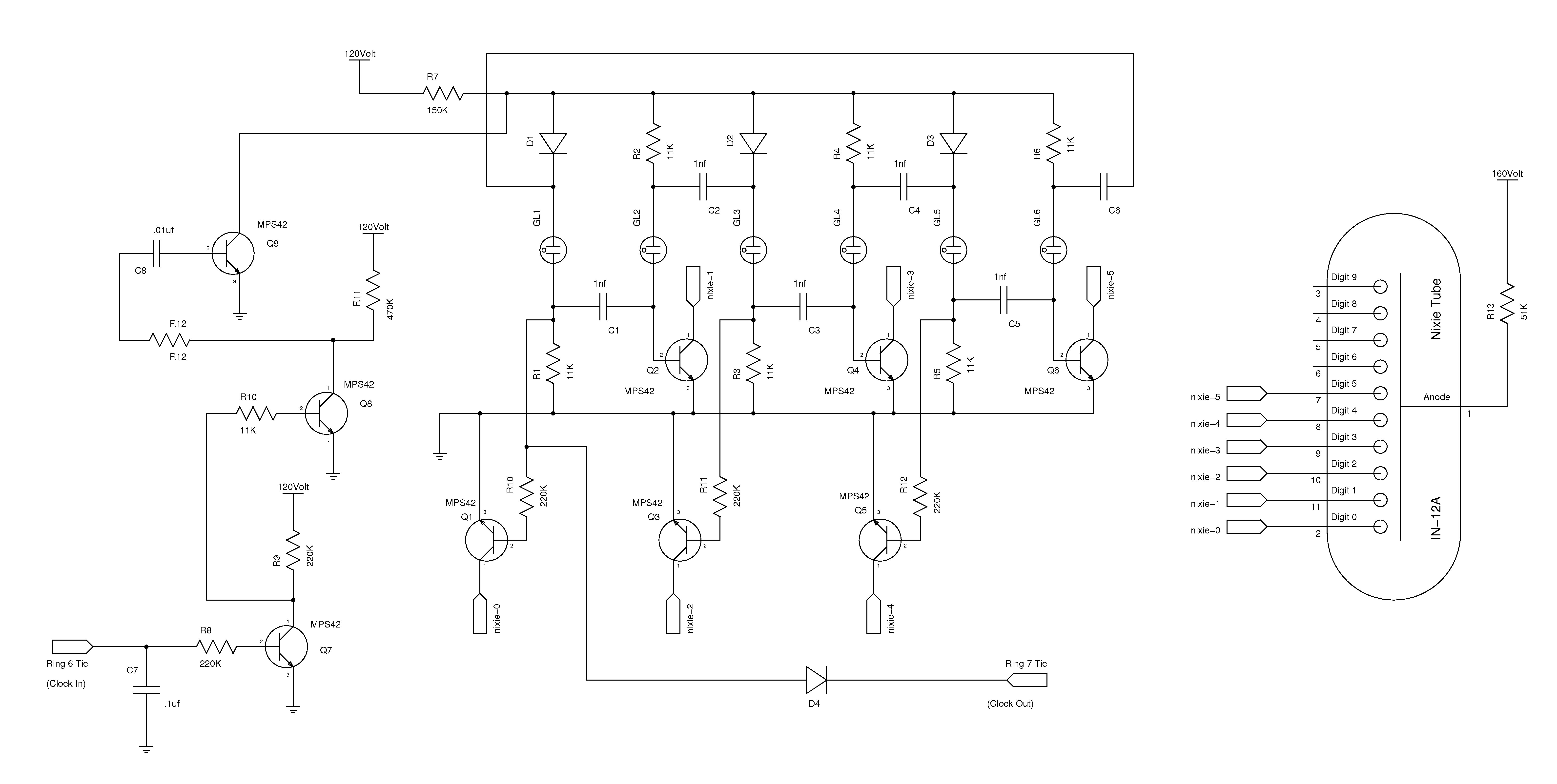
The nixie tube clock consists of a high-voltage power supply, seven ring counters, and an Atmel AVR processor. The power supply is shown in Schematic 1. It takes 12 volts AC and converts it to DC, which drives the...
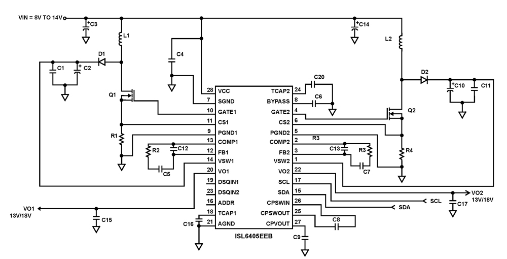
The ISL6405 is a highly integrated voltage regulator and interface integrated circuit (IC) designed to supply power and control signals from advanced satellite set-top box (STB) modules to the low noise blocks (LNBs) of two antenna ports. This device...
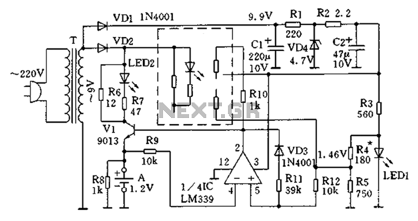
The circuit operates for 10 hours using constant current charging, providing convenience. The electricity from the secondary transformer T is stepped down, with the output directed through VD1 for rectification, followed by R1 and C1 for filtering. VD4 regulates...
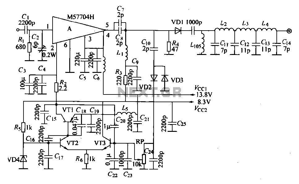
The FM radio transmitter is a high-frequency amplifier circuit that utilizes the Mitsubishi frequency set, specifically the M57704H discharge path. It operates within the frequency range of 457-458 MHz and has a transmission power of 5 watts. As illustrated...
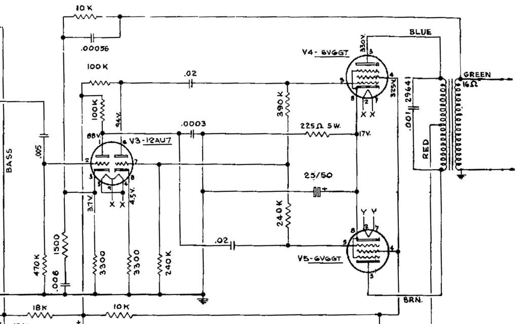
This schematic has been modified from an old Bell & Howell projector amplifier for model 302, utilizing PP 6V6 tubes with a 12AU7 phase inverter (PI). The PI circuit appears to be closest to a "floating paraphase." There is...
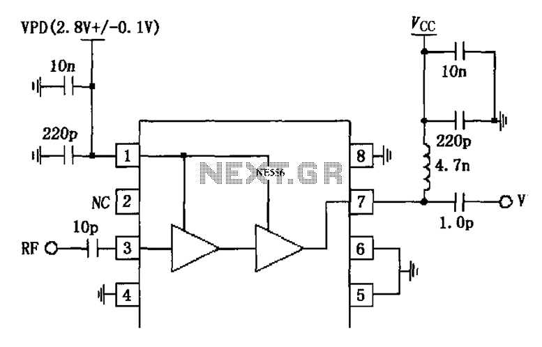
The circuit is constituted by the RF2324 1880MHz internal amplifier collector bias application. A radio frequency (RF) signal enters through input pin 3 and is processed by a preamplifier. The final stage power amplifier output is amplified by 7...
Warning: include(partials/cookie-banner.php): Failed to open stream: Permission denied in /var/www/html/nextgr/view-circuit.php on line 713
Warning: include(): Failed opening 'partials/cookie-banner.php' for inclusion (include_path='.:/usr/share/php') in /var/www/html/nextgr/view-circuit.php on line 713