
Quick NiCd - NiMH Charger
The input voltage must be at least 3 times the battery's voltage. For example, an input voltage of 25V can charge an 8.4V (9V) battery.
R3 is 1/2 Watt and R1 and R2 are 1/4 Watt.
The circuit utilizes the LM317 voltage regulator, which is a versatile component capable of providing a stable output voltage. The LM317 operates in the adjustable mode, allowing it to regulate the output voltage based on the resistors R1 and R2, which are configured in a voltage divider arrangement. The adjustment pin of the LM317 is crucial for setting the output voltage, which in turn determines the charging current supplied to the connected battery.
When a battery is connected to any of the designated pins (JP1-JP4, JP2-JP4, or JP3-JP4), the charging process initiates. The current flowing through R1 creates a voltage drop, which is essential for the operation of the subsequent components in the circuit. The diode D1, with a forward voltage drop of approximately 0.7 volts, allows current to pass while blocking reverse current flow, ensuring that the battery does not discharge back into the circuit. The transistor Q1 acts as a switch controlled by the output from the LM317, allowing current to flow to the battery when it is charging.
Resistors R1, R2, and R3 play a critical role in determining the charging current. The formula provided, Rx=(1.25 + 0.1) / I, highlights how the resistance values can be calculated based on the desired charging current, which is set to 1/10 of the battery's capacity. This method ensures that the charging current is appropriate for the battery being charged, preventing overcharging or damage.
The design specifies that the input voltage must be at least three times the voltage of the battery to ensure proper operation of the LM317. For instance, a battery with a nominal voltage of 8.4 volts would require a minimum input voltage of 25.2 volts for effective charging.
Power ratings for the resistors are also specified, with R3 rated at 1/2 Watt and R1 and R2 at 1/4 Watt, ensuring that they can handle the power dissipation without overheating during operation. This attention to component ratings is essential for the reliability and longevity of the charging circuit.The charger is build around a LM317 (click to download datasheet) adjustable regulator. The charge starts when a battery is connected between pins JP1-JP4 or JP2-JP4 or JP3-JP4. For example, if a battery is connected to JP1-JP4 pins then the current that flows cause a voltage drop to R1, then D1 causes a voltage drop of 0,7 volts and ?1 conducts. Then through transistor's emitter flows a current that comes from Adjustment pin of LM317. Diode D4 prevents current to flow from battery back to the charging circuit. Resistors R1,R2 and R3 adjusts the charging current and it's value is given from : Rx=(1,25 + 0,1) / I , where x = 1,2,3.
I is 1/10 of the battery's charging capacity. For example if battery has a rated capacity of 1700mA then ?=170. The input voltage must be at least 3 times the battery's voltage. For example an input voltage of 25V can charge a 8,4V (9V) battery. R3 is 1/2 Watt and R1 and R2 it's 1/4 Watt. 🔗 External reference
Related Circuits
It can safely charge a 7-cell RC2000 pack in about 14 minutes, and an RC2400 or CP2400SCR pack in about 17 minutes. As a NiCd cell is being charged, two things happen which affect its temperature. Due to resistive...
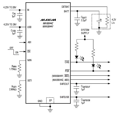
The MAX8844 lithium-ion charger integrated circuit (IC) from Maxim Semiconductors facilitates the design of a simple and efficient charger circuit for a single-cell lithium-ion battery. This charger integrates a current-sense circuit, a MOSFET pass element, thermal-regulation circuitry, and eliminates...
It's just a simple power supply with a 7805 regulator. The chip must be mounted on a large metal radiator because the current requested by the regulator is near 0.4 A. However, to lower the power, you can put...
This circuit can be used to charge accumulator and cell batteries. It features a very stable output that extends the battery life and maximizes the added battery capacity. The charging process is also quite fast, optimizing the time required...
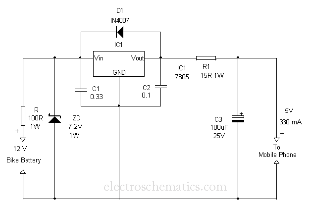
This circuit provides a simple and efficient method to draw current from a motorcycle battery to charge a mobile phone. Most mobile phone battery packs consist of three 1.2-volt cells, resulting in a total voltage of 3.6 volts. For...
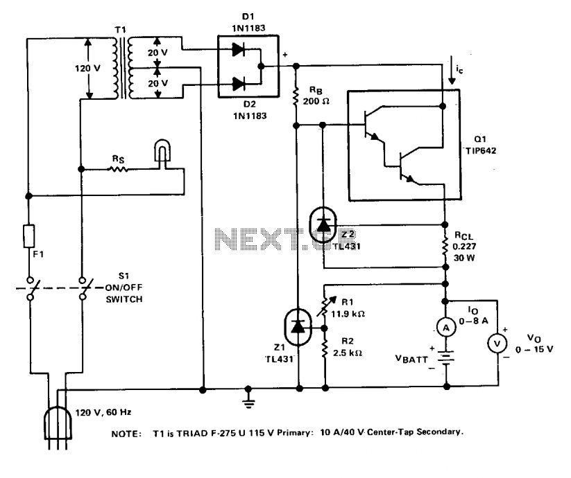
The charger operates with a charging voltage of 2.4 V per cell, aligning with the recommendations of most manufacturers. The circuit delivers a charging voltage of 14.4 V (6 cells at 2.4 V per cell) in a pulsed manner...