
Quiz Project
The electronic schematic for this quiz project features a straightforward layout focused on functionality and user interaction. The primary components include four 555 timer ICs configured as bistable multivibrators, which are pivotal for the operation of the trigger switches and LED indicators.
Each bistable multivibrator is connected to a trigger switch, ensuring that pressing the switch sends a momentary pulse to the trigger pin (pin 2) of the 555 timer. The inclusion of a 0.1 µF capacitor in the circuit serves to filter out any noise and allows for edge triggering, ensuring that only the initial press of the switch is registered by the bistable, thus preventing accidental multiple triggers from a sustained press.
The reset functionality is centralized, allowing the quizmaster to reset all bistables simultaneously. This is achieved by tying the reset pins of all four 555 timers together, which are activated by a single push-switch. This design choice enhances the user experience, enabling a smooth transition between quiz questions.
The output from each bistable (pin 3) is connected to an LED, providing a visual indication of which contestant has pressed their switch first. Additionally, the output is linked to a trigger line that is kept high to inhibit further triggering of other bistables, ensuring that only one contestant can be recognized at a time. The incorporation of a diode in the output connection prevents feedback into the trigger line, maintaining the integrity of the circuit operation.
Overall, the circuit is designed for reliability and ease of use, making it suitable for quiz competitions. The careful arrangement of components on the stripboard, along with the option for flexible wiring for the trigger switches, enhances the practicality of the project, allowing for a competitive and engaging quiz experience.This project can be used for a quiz with up to 4 contestants (or teams). Each contestant has a trigger push-switch and LED. When a trigger switch is pressed it lights the corresponding LED, sounds the bleeper and prevents the other trigger switches from working - therefore showing which contestant was the first to press their switch. A reset push- switch (operated by the quizmaster) cancels the bleeper and switches off the LED so the circuit is ready for the next question. Take great care to arrange the parts correctly on the compact stripboard layout. The LEDs are shown mounted directly on the stripboard but you may prefer to mount them on a box using short wires.
The trigger switches need long cables of about 2 metres so they can be held by, or placed near, the contestants. The circuit consists of four 555timerbistables which are triggered or reset when their inputs are low.
Their reset inputs are connected together and operated by a single reset push-switch. The trigger switches are connected to the bistable trigger (pin 2) through a 0. 1 µF capacitor so that only the initial press triggers the bistable; continuing to hold the switch closed will have no effect. This is called edge triggering. Connecting the switch directly to the bistable would prevent the quizmaster from resetting the circuit until the trigger switch was released and trials showed that many contestants kept the switch pressed until asked to give their answer!
When triggered the bistable output (pin 3) lights an LED and makes the `trigger line` high - this prevents any other bistable being triggered and sounds the bleeper. A diode is used to link the output to the trigger line. 🔗 External reference
Related Circuits

The operation of the rain alarm circuit is explained in detail. The rain alarm project is outlined along with a circuit diagram. The rain alarm circuit is designed to detect the presence of rain and alert users through an audible...

This simple wind charger circuit project is designed using the LTC1042 monolithic CMOS window comparator, manufactured by Linear Technology. The wind charger circuit utilizes wind power to generate the energy necessary for charging Ni-Cd or lead-acid batteries. When the...
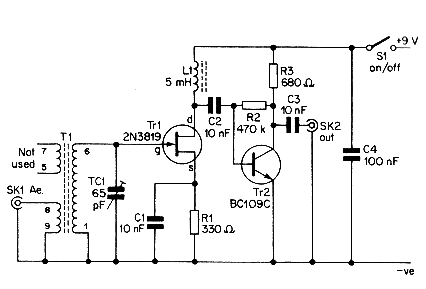
This simple aerial booster circuit design could serve as an alternative or a hobby project for creating an aerial booster device for Citizen Band (CB) radio. The aerial booster circuit is designed to enhance the performance of Citizen Band (CB)...
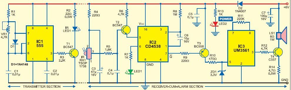
This burglar alarm system circuit utilizes an infrared proximity detector that triggers an alarm when the rays falling on its sensor are interrupted. It stands out from other burglar alarm systems due to its simplicity as a DIY project,...
The project described is a digital implementation of the book cricket game, which is commonly played by Indian students during their childhood. The core component of the project is an 8-bit microcontroller from the AVR family known as the...
This is a quiz bell/alarm circuit designed to indicate the fastest finger first. The circuit includes one bulb for the quiz master and one for each contestant. The bulbs illuminate when a button is pressed. The cathode of the...
Warning: include(partials/cookie-banner.php): Failed to open stream: Permission denied in /var/www/html/nextgr/view-circuit.php on line 713
Warning: include(): Failed opening 'partials/cookie-banner.php' for inclusion (include_path='.:/usr/share/php') in /var/www/html/nextgr/view-circuit.php on line 713