
Radio Buttons Using Push On Switch Latching Circuit
The switching circuit operates on the principle of latching, allowing multiple push buttons to function as a set of radio buttons. When one button is pressed, it activates the interlocking circuit, ensuring that only one button remains active at any given time. This is achieved through a combination of resistors, transistors, and possibly diodes, which work together to maintain the state of the last button pressed while deactivating the others.
The circuit typically includes a power source, which energizes the components, and a ground connection to complete the circuit. Each push button is connected to a transistor that serves as a switch. When a button is pressed, it sends a signal to the base of the corresponding transistor, allowing current to flow from the collector to the emitter, thus turning it on. The interlocking mechanism is established by connecting the output of each transistor to the base of the others, creating a feedback loop that ensures only one can be active.
Additional components may include pull-down resistors to prevent floating states when buttons are not pressed, and capacitors for debouncing to eliminate noise from mechanical switch contacts. This design is particularly useful in applications where a user must select one option from a set, such as in user interfaces for electronic devices, ensuring a clear and intuitive operation.This is a switching circuit that provide latching mechanism to make a set of radio buttons using push buttons. This circuit consist of interlocking circuit.. 🔗 External reference
Related Circuits
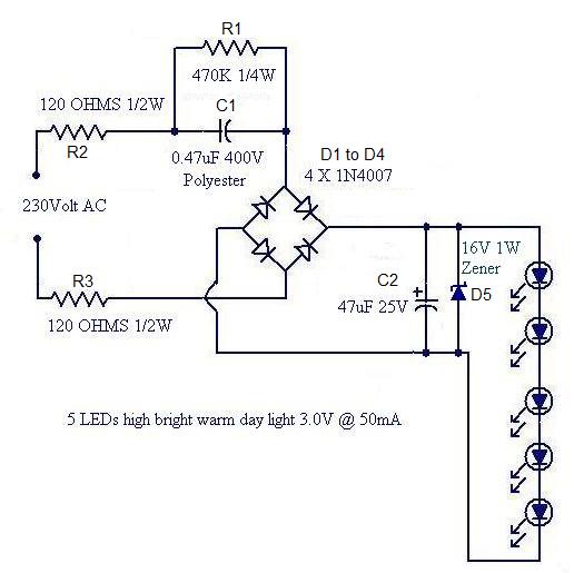
Convert a used CFL into a power-saving LED lamp circuit that consumes only 50mA. This gadget can be used in applications like a night light, table lamp, etc. The project involves redesigning a compact fluorescent lamp (CFL) to function as...
Audio light modulations add to the enjoyment of music during functions organised at home or outdoors. Presented here is one such simple circuit in which light is modulated using a small fraction of the audio output from the speaker...
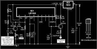
This is a circuit diagram for automatic muting in audio systems utilizing the IC LB1403. The output from a pre-amplifier, such as the LA3160, LA3161, or HA1032, is connected to the base of the amplifier transistor BC548 (T1). A...
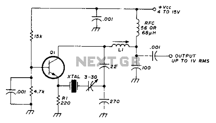
A circuit diagram illustrating the reliability of crystal startup, with power consumption significantly lower than the maximum allowed for the crystal. The transistor Q1 can be one of the following: 2N918, 2N3564, 2N5770, BF180, or BF200. The inductor L1...
This circuit activates an alarm when its sensor comes into contact with water. It employs a 555 astable multivibrator that generates a tone of approximately 1 kHz upon water detection. The circuit consists of a 555 timer configured in astable...
The following circuit illustrates the use of a 555 integrated circuit (IC) for an infrared (IR) remote control extender circuit. Features include support for 850 nm and 950 nm signal wavelengths, along with the capability to generate control pulses. The...