
radio frequency rf watt meter circuit

The RF watt meter circuit serves as a critical tool for evaluating and optimizing RF transmitter performance. Its design allows for versatility across various HF bands, providing reliable measurements regardless of frequency. The circuit's sensitivity is a key factor; it is primarily determined by the mechanical characteristics of the meter movement, the inductive coupling through the primary coil, and the resistive voltage divider that influences the voltage drop across the meter.
The inclusion of adjustable potentiometers enables users to scale the watt meter's output to specific wattage ranges, enhancing usability for different transmitter power levels. The capacitors C1 and C2 play a vital role in tuning the circuit to achieve precise measurements, allowing for the fine-tuning of the watt meter's response. The specified diodes, 1N34A and 1N60, are chosen for their low forward voltage drop and fast switching capabilities, ensuring accurate rectification of the RF signals.
The inductor L1, constructed with 46 turns of No. 28 wire, provides the necessary inductance for the RF watt meter's operation. The additional 2 turns of No. 22 wire create a secondary inductor L2, which may assist in achieving the desired impedance matching and signal coupling.
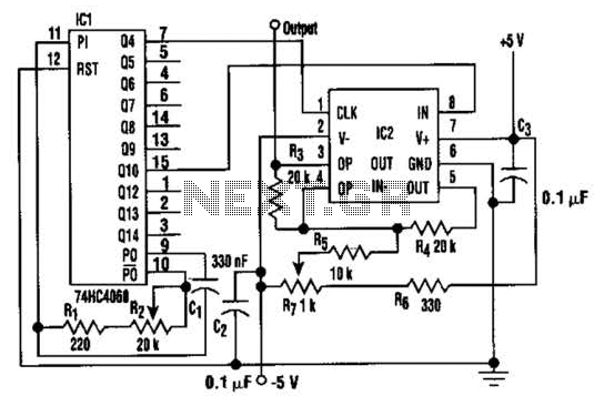
The calibration process outlined in the description is crucial for ensuring the accuracy of the watt meter. By adjusting the circuit components as specified, users can achieve a null reading, confirming that the meter is correctly calibrated to reflect the power levels being transmitted. This calibration not only enhances measurement accuracy but also contributes to the overall efficiency of the RF transmitter system. Proper implementation of this circuit can lead to improved performance and reliability in various RF applications.This is a circuit for RF (radio frequency) transmitter experiment, watt meter is useful for optimizing the transmitter circuit. A simple RF watt meter circuit is shown in the schematic diagram below. Because circuit is not frequency sensitive, calibration is accurate on all HF bands. The sensitivity is affected by meter movement, number of turns i n primary coil, and resistive voltage driver. This is the figure of the system; Pots can be adjusted for full-scale values from 1-14 W with values shown on the diagram. C1 and C2 are 3-20 pF. Diodes are 1N34A, 1N60, or equivalent. L1 is 46 turns No. 28 on Amidon T-50-2 toroid, with 2 turns No. 22 between ends of L1 for L2. Connect resistive dummy load to one coax receptacle and RF power source to other to adjust, with R2 at maximum resistance.
We can provide highest meter reading and make that the FWD position with place the switch on the upper position. Switch to other position, which becomes REF, and for null reading, adjust C1. Reverse RF source and load, leaving switch at FWD, and adjust C2 for null. Now, we can calibrated the Wattmeter. 🔗 External reference
Related Circuits
A modulated current is supplied by the integrated rotational speed sensor KMI 15/x. This current signal needs to be converted into a ground-referenced voltage signal. The KMI 15/x sensor operates by generating a modulated current proportional to the rotational speed of...
The following circuit is an example of how to get power from an RS-232 serial port. It provides regulated +5V power for logic circuits and also unregulated positive and negative power supplies for the RS-232 transmitting circuit. The circuit...
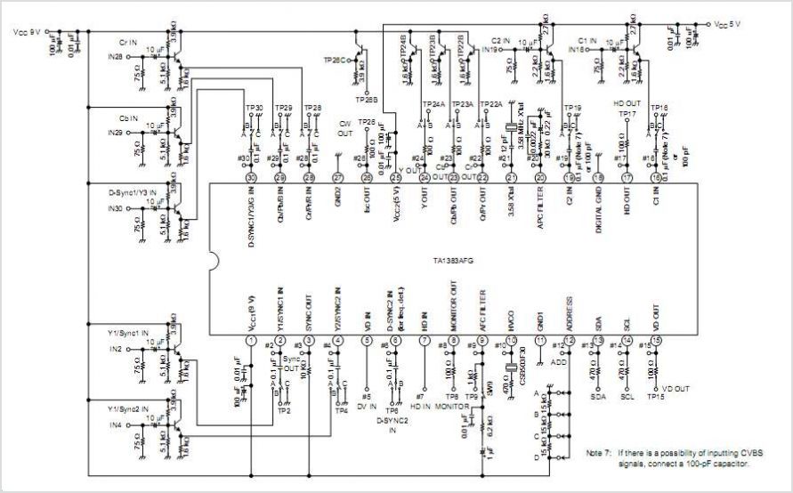
The TA2003PG and TA2003FG are integrated circuits designed for AM/FM radio applications. These ICs facilitate AM/FM radio functionality, including FM front-end and AM/FM intermediate frequency processing. When combined with the TA7368P mono power amplifier IC, a comprehensive AM/FM radio...
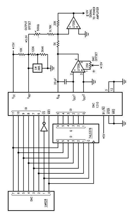
The LM628 and LM629 dedicated motion-control processors can be utilized to design various applications involving DC and brushless DC servo motors, as well as other servomechanisms. The power path of this electronic project, which functions as a motor driver,...
In this circuit, a square wave is filtered using a high-order low-pass filter designed to eliminate most harmonics of the waveform at a -3 dB frequency. Consequently, the output of the filter is a fundamental sine wave. This technique...
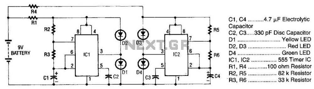
The super LED flasher consists of two complete LED flasher circuits integrated onto a single circuit board. The first LED flasher is comprised of IC1 and LEDs D1 and D2. IC1 is a 555 timer IC configured as an...