
Railway circuits

The Pug locomotive was modified by cutting the weight horizontally from front to back and reducing the top section to accommodate the decoder, specifically a Digitrax DH121. If this modification were to be done today, a DZ123 decoder, which is significantly smaller and sufficiently powerful for the Pug, would be chosen. Point motors were mounted beneath the baseboard instead of directly on the points, which initially caused alignment issues due to short actuator pins. To resolve this, the pins were extended using 1.2mm piano wire crimped to the pin with 3mm brass tubing. To properly align the motor with the point, two 2mm holes were drilled through diagonally opposite tab slots in the point, allowing the tabs of the point motor to be adjusted. The straight tabs were pushed through the baseboard after aligning the extended actuator pin with the point's drawbar and secured in place with screws.
The described DCC system facilitates a streamlined approach to model railway control, allowing multiple locomotives to operate simultaneously without complex wiring configurations. The bus wiring method enhances the reliability of power distribution across the layout, minimizing the risk of electrical interference and ensuring consistent performance. The use of readily available materials, such as speaker wire, exemplifies a practical approach to model railroading, while the consideration of color-coding for wire identification aids in maintenance and troubleshooting.
The modifications made to the Pug locomotive demonstrate an understanding of both mechanical and electronic integration within model railroading. The choice of decoders reflects a balance between size constraints and power requirements, ensuring that the locomotive operates efficiently. The innovative solution for mounting point motors beneath the baseboard highlights the importance of precision in model construction, as well as the need for adaptability when addressing mechanical challenges. Overall, this approach showcases a thoughtful integration of technology and craftsmanship in the realm of model railroading.Digital Command Control, for those who don`t know, offers many advantages over conventional DC analogue control systems. The main one being the simplicity of wiring. DCC allows one to control many locomotives individually on the layout without having to electrically isolate parts of the track.
The only exceptions being the number of locomotives dr awing current from the track and reverse loops. I wont go into too much detail here since there are plenty of other web sites devoted to this. For the layout I`ve adopted a "Bus" wiring method whereby a pair of wires carrying the DCC power/signal (the bus) is run around under the layout and tapped with feeds from the track. No particular reason for using speaker wire other than that it seemed silly to go out and buy special wire when I had great knotted balls of speaker wire cluttering up the wardrobe.
If I was buying wire specially for the job I would probably use black and red pair, thick for the bus and not so thick for the feeds, just to make it easier to identify which rail is going to which side of the bus pair. As it is the feed wires are a little thick and obtrusive where they are soldered onto the track. The Pug disassembled. I had to cut the weight horizontally from front to back then cut the top piece down to fit the decoder in.
The decoder is a Digitrax DH121. If I was doing it today I`d use a DZ123, which is a quarter of the size and has ample power for a little Pug. I mounted point motors under the baseboard rather than directly to the bottom of the points. This initially presented some problems because firstly the actuator pins were too short and secondly it was very difficult to line them up with the point.
I extended the pins by crimping some 1. 2mm piano wire onto the pin with some 3mm brass tubing (sorry, no pictures of this). To line the motor up with the point I drilled two 2mm holes through diagonally opposite tab slots in the point straight down through the baseboard. I then bent the oposing tabs on the point motor outward at right angles, leaving the corresponding tabs straight.
I pushed the straight tabs up through the holes in the baseboard (after carefully locating the extended actuator pin thorugh the hole in the point`s draw bar) and fastened the bent tabs to the baseboard with screws. 🔗 External reference
Related Circuits
Basic information on the construction of various types of lasers from scratch, including topics such as home-built laser safety, setting up a home laser lab, sources of supplies and chemicals, vacuum systems, glass working, structural materials, power supplies, and...

The circuit is a high-power car audio amplifier schematic. It functions as a car audio amplifier using the PA02 and LH0101 integrated circuits (ICs). Each IC delivers an output power of 30W with an 8-ohm impedance. The part list...
Activated this and inadvertently destroyed several 2N3055 transistors by shorting the emitters to ground. In all cases, the transistors opened up, and no damage to the emitter occurred in any transistor. The alternative circuit in Figure 2 will provide...
Electrical signals travel along the neurons in the brain and body, continuously transmitting information throughout the complex system. Without these signals, the body would function like a plant, with different parts unaware of each other's conditions, making animal life...
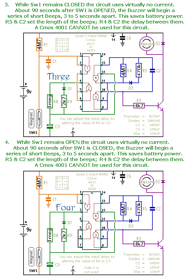
This document presents a collection of compact, self-contained alarm circuits. These circuits are designed to operate with a very low standby current, making them ideal for battery-powered applications. They can be triggered by both normally-open and normally-closed switches, while...
A digital audio frequency (AF) counter can be constructed using a minimal number of components by employing a single 7226B integrated circuit (IC) from Intensil, as depicted in the accompanying diagram. This circuit has an upper frequency limit of...