
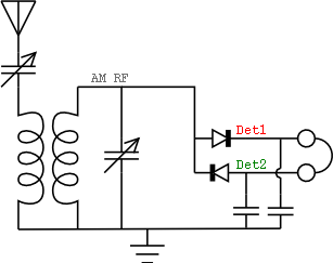
Receiver monitor
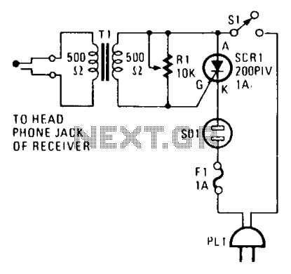
The circuit operates by utilizing a silicon-controlled rectifier (SCR) as the primary switching element. The SCR, designated as SCR1, is triggered by a specific audio signal that is normally directed to headphones. This setup allows the circuit to monitor the audio signal actively. When the designated signal is detected, it is fed to the gate of SCR1, causing it to enter a conductive state. Once activated, SCR1 completes the circuit to the signaling device, which can be configured as either an audible alarm (such as a buzzer or speaker) or a visual indicator (such as an LED lamp).
The inclusion of the variable resistor R1 is critical for fine-tuning the sensitivity of the circuit. By adjusting R1, the user can set a threshold that determines how sensitive the alarm is to environmental sounds. This prevents nuisance alarms caused by background noise, ensuring that only significant audio signals trigger the alarm.
In terms of connectivity, the circuit is designed to plug directly into the earphone jack of the receiver, making it easy to integrate with existing audio equipment. The output from SCR1 can be connected to various types of alarms depending on the application requirements.
Overall, this design offers a flexible and effective solution for monitoring audio signals and providing alerts while minimizing false triggers from ambient noise.The alarm plugs into the earphone jack on a receiver. Then when a signal (normally fed to the headphones) is detected and applied to the gate of SCR1, it conducts, sounding whatever alarm is connected to SOI. The signaling device can be an audible alarm or a lamp. Variable resistor Rl functions as a sensitivity control so that background noises won't trigger the alarm. 🔗 External reference
Related Circuits
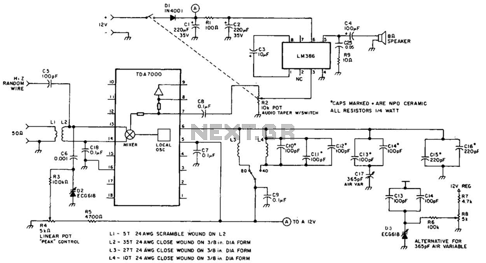
This direct-conversion receiver utilizes a TDA7000 integrated circuit (IC) and incorporates an LM386 audio amplifier. The TDA7000 serves as the mixer and local oscillator (L.O.) section. The frequency control can be achieved using either an air variable capacitor or...
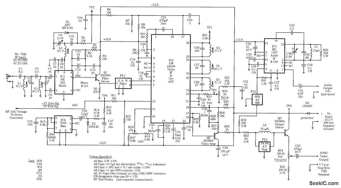
This intermediate frequency (IF) system employs a NE602 oscillator/mixer to convert VHF television signals ranging from 60 to 72 MHz (channel 13 or channel 4 under the U.S. NTSC standard) down to 45 MHz. A surface acoustic wave (SAW)...
This is a simple non-contact AC power monitor designed for home appliances and laboratory equipment that should remain continuously powered. A failure of the fuse or a power outage in the equipment can lead to significant damage if unnoticed....
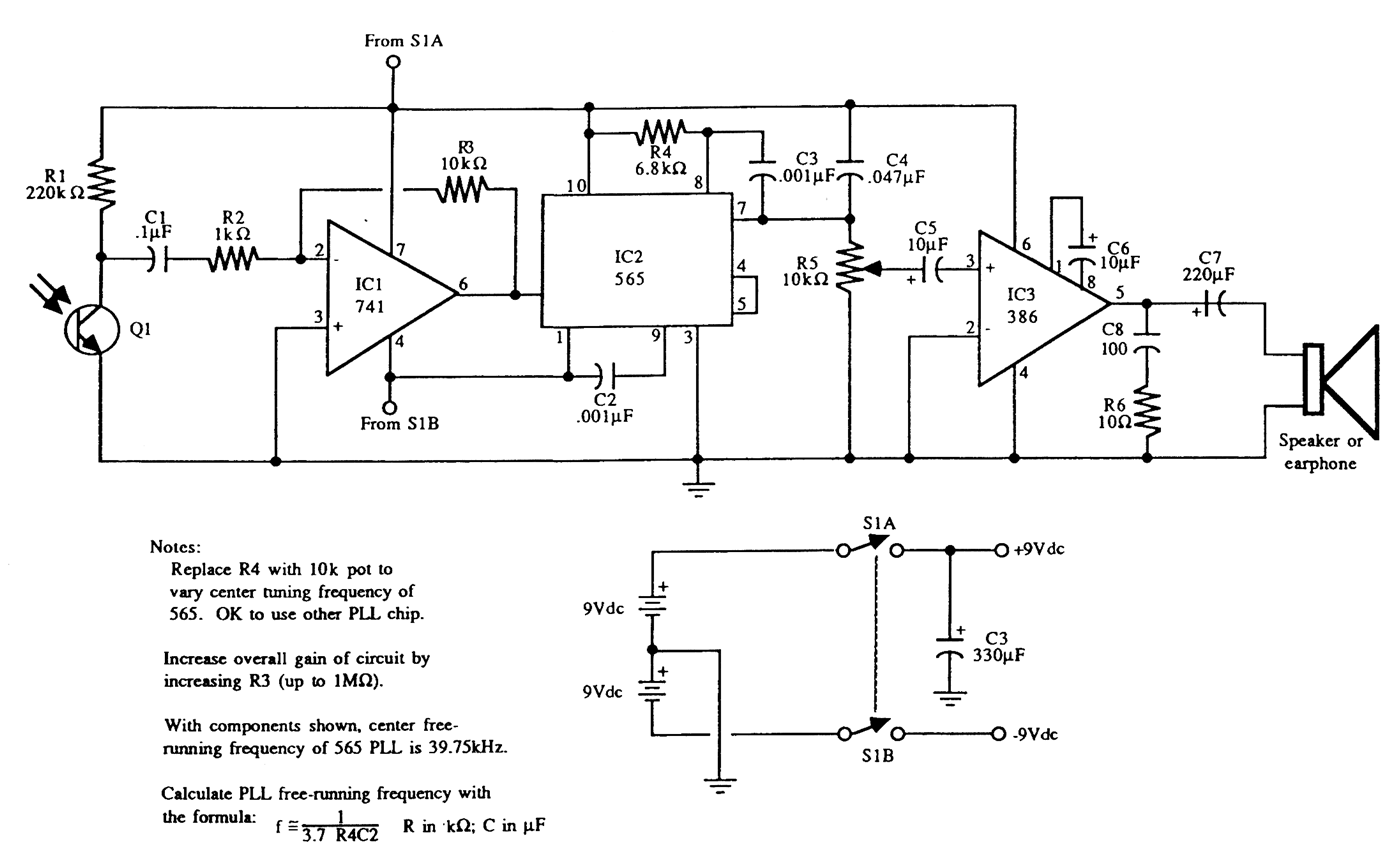
Circuit schematics for the 555-based PLL laser light PFM receiver. Although R4 is shown as a resistor, it is advisable to replace it with a 10-kΩ precision potentiometer to allow for fine-tuning of the transmitter's center frequency. Experimentation with...
There are instances when a radio station can be found, and other times when no stations are detectable. The primary issue while tuning appears to be that any movement of the hands or body, such as releasing the tuning...
The concept of the passive receiver dates back over a century. The earliest known type of receiver capable of detecting radio energy is the coherer, which was invented by Edouard Branly. This primitive radio signal detector, used in the...
Warning: include(partials/cookie-banner.php): Failed to open stream: Permission denied in /var/www/html/nextgr/view-circuit.php on line 713
Warning: include(): Failed opening 'partials/cookie-banner.php' for inclusion (include_path='.:/usr/share/php') in /var/www/html/nextgr/view-circuit.php on line 713