
Regency ATC-1 Converter
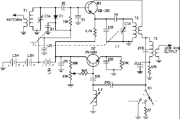
The Regency ATC-1 converter circuit is a testament to early transistor technology in amateur radio. The circuit design incorporates two key transistors: a PNP transistor (commonly used for amplification) and an NPN transistor (often utilized for switching and signal processing). The circuit configuration allows for efficient frequency conversion, enabling the reception of various amateur radio bands. The Q-multiplier enhances AM reception by improving selectivity and sensitivity, while the Beat Frequency Oscillator (BFO) facilitates Single Sideband (SSB) and Continuous Wave (CW) reception, both vital for effective communication in amateur radio.
The power supply design, utilizing three AA batteries, exemplifies the focus on portability and convenience, allowing operators to use the ATC-1 in mobile settings without the need for bulky external power sources. The tuning mechanism, featuring a rotating drum, provides visual feedback on the selected band, ensuring ease of use during operation. The calibration of the dial marks every 10 kHz enables operators to fine-tune their frequency selection accurately.
In summary, the Regency ATC-1 converter not only represents a significant advancement in the field of amateur radio but also reflects the broader transition from vacuum tube technology to transistor-based designs. Its introduction marked a pivotal moment in radio history, paving the way for future innovations that would ultimately lead to the widespread adoption of transistor technology in various electronic applications.The 1956 Regency ATC-1 converter heralded the dawn of a new era for amateur radio. The little converter had only two transistors - one PNP, one NPN, both germanium, both now long obsolete - but they were the start of a revolution. Amateurs responding to the Regency advertisement in the August 1956 issue of CQ Magazine thought they were merely bu
ying a novel mobile converter. In truth, for $79. 50, they were buying a seminal piece of ham radio history. Regency Electronics was the brainchild of former RCA employees, Joe Weaver and John Pies. The parent company, Industrial Development Engineering Associates (I. D. E. A), was incorporated in 1947, the same year Bell Labs scientists Shockley, Bardeen and Brattain invented the transistor. In October, 1954, Regency brought to market the world`s first transistor radio, the TR-1, and less than two years later, the world`s first transistor amateur product, the ATC-1 converter.
Unbeknownst to all, this inauspicious little device signaled for amateur radio the beginning of the end of the vacuum tube`s long and glorious reign. The ATC-1 was intended to fill a niche market for mobile operators. When Regency introduced its new converter in 1956, most hams used dedicated receivers in their vehicles, the Multi-Elmac PMR-7, the Morrow MBR-5, and the Gonset G-66 being popular mobile receivers of the day.
Other companies` mobile HF converters, such as the Gonset "tri-band Converter" had never been big sellers, primarily because their vacuum tube designs offered little space savings over full-blown receivers. Furthermore, like all mobile receivers, vacuum tube converters required an external power supply. Regency obviously hoped that the diminuative, battery-powered ATC-1 would reverse this record. Powered by three AA penlight cells, the ATC-1 covered five bands (80-10 meters) and featured a Q-multiplier for AM reception and a BFO for SSB/CW reception.
A rotating drum displayed the band in use, with single-knob tuning. Bandspread was quite adequate, with dial calibration marks every 10 kHz. The output frequency of the converter was 1230 kHz. Top view of the ATC-1 with the cover removed, showing the dial drum mechanism and the indvidual tuned circuits at the emitter of mixer/oscillator transistor Q1. Despite its simplicity, the ATC-1 was a remarkable engineering achievement. To appreciate fully this achievement, however, it is necessary to place the ATC-1`s design into historical context.
In the mid-fifties, the transistor`s advantage over vacuum tubes was primarily in simple, portable applications, where size and power consumption were important but performance secondary. For most applications, vacuum tubes had a head start of nearly a half century, and it seemed highly improbable that transistor technology could ever catch up.
Transistor usage in r. f. applications seemed particularly problemmatic. Secondly, many engineers schooled in tube circuits found transistor circuits alien and confusing. Unlike vacuum tubes, transistors were current-operated devices. Their impedances were very low, there was little isolation between inputs and outputs, and they were prone to thermal runaway. To design with these fragile little devices, the rules of thumb, the guidelines, and the intuition developed over a professional career had to be tossed out the window.
Transistors were a whole new ballgame, and the learning curve was steep. And finally, the germanium transistors of the 1950s were unimpressive performers. Their current gain was low, as was their frequency response, and they were highly temperature sensitive. And worst of all, they were oh-so-delicate. A slip of a cliplead, a tiny snap of static electricity, a battery momentarily connected backwards, and they would be gone in an eyeblink.
And to make matters worse, these early transistors cost several dollars apiece. Frankly, to many design engineers, transistors were such poor performers t 🔗 External reference
Related Circuits

In this circuit, an LM34 or LM35 generates a frequency that is proportional to temperature. The reference current (138) is established through resistor R3. The output can be utilized to drive a display, frequency counter, or other indicating devices...

This document serves as a resource for developers who are new to Texas Instruments (TI) ARM-based processors, as well as for seasoned developers seeking to deepen their understanding of the different ARM architectures. It starts with an overview of...
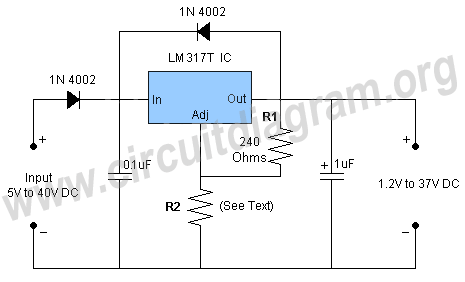
This is a simple circuit of a DC to DC converter utilizing the LM317T integrated circuit (IC). The LM317 is a well-known IC that comes in a TO-220 package. This high-performance IC features an input voltage range of 3...
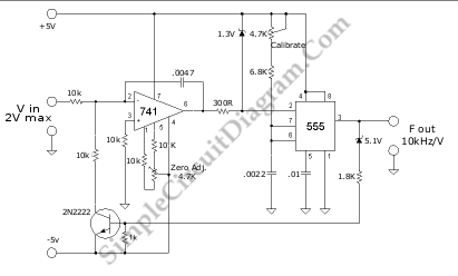
A voltage-to-frequency converter (VFC) circuit is depicted in the schematic diagram below. The circuit utilizes a 555 integrated circuit (IC) as the core component for its operation. The voltage-to-frequency converter is a crucial component in various analog and digital...

This is a DC regulator circuit that can provide multiple output voltages simply. It functions as a simple step-down DC converter and is designed with a fixed resistor R1. The described circuit operates as a DC voltage regulator, specifically designed...
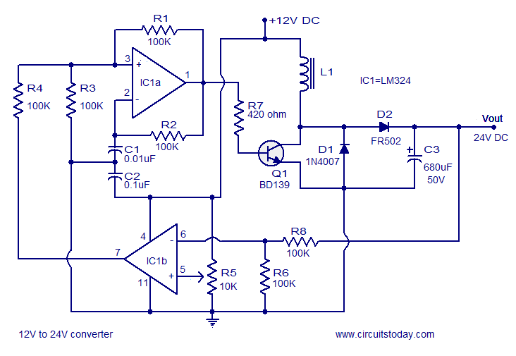
A simple 12V to 24V DC-DC converter circuit diagram built around the LM324. This boost converter schematic can provide up to 800mA output current and a steady 24V DC. The described circuit utilizes the LM324 operational amplifier as the core...