REGENERATIVE_SHORTWAVE_RECEIVER

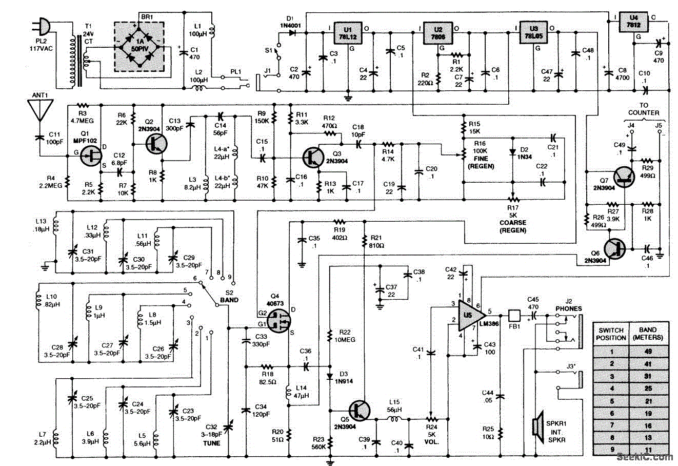
The receiver consists of multiple subassemblies, including an active antenna, an amplifier featuring regeneration control and band-switching circuitry, an AM detector, a power amplifier, and an output device such as an internal speaker, external speaker, or headphones. Additionally, it is equipped with a multivoltage power supply. The schematic diagram of the receiver is illustrated in the accompanying figure.
The receiver architecture is designed to effectively capture and process amplitude modulated (AM) signals. The active antenna serves as the initial point of signal acquisition, converting electromagnetic waves into electrical signals. This signal is then fed into the amplifier, which is responsible for boosting the signal strength. The amplifier incorporates regeneration control, allowing for the enhancement of weak signals while minimizing noise, and band-switching circuitry, facilitating operation across various frequency bands.
Following amplification, the AM detector demodulates the signal, extracting the audio information carried by the carrier wave. The output from the detector is then directed to the power amplifier, which further increases the signal strength to drive the output device. Depending on the design, the output device may be an internal speaker, an external speaker, or headphones, enabling the user to hear the demodulated audio signal.
The multivoltage power supply ensures that all components of the receiver operate efficiently, providing the necessary voltage levels for optimal performance. The schematic diagram provides a visual representation of the interconnections between these components, illustrating how the receiver processes incoming signals from the antenna to the output device. This comprehensive design allows for versatile use in various applications, enhancing the user experience in receiving AM broadcasts.The receiver is composed of several subassemblies: an active antenna, an amplifier (with a regeneration control and band-switching circuitry), an AM detector, a power amplifier, and some form of output device (internal speaker, external speaker, or phones), plus a multivoltage power supply. The schematic diagram of the receiver is shown in the figure, a dual.. 🔗 External reference

