
Regentonmeter
This project illustrates various features of the PIC16F687 microcontroller, including ultra-low power wake-up, serial communications, and nanowatt technology. The device can serve multiple purposes, such as measuring the water level in a rainwater tank or a water tank in a motorhome or trailer. The sensor wires are placed in the tank. After inserting the batteries, the water level is displayed on a bar-graph display (ranging from 1/8 to 8/8). The display turns off automatically after about a minute but can be reactivated by briefly pressing a button. To turn it off, the button must be held for more than one second. Once an hour, the display will briefly turn on, during which the device can transmit the measured value using RF (433.92 MHz) optionally. The transmitter/measuring module can operate independently or in conjunction with an optional receiver module that functions on 230 VAC. This receiver module can be positioned within a 30-meter radius of the transmitter/measuring module. Diode D2 protects against reverse polarity of the batteries and slightly reduces the supply voltage. Two lithium batteries are intended to provide 6 volts, but the actual output is approximately 6.2 volts with new batteries. The voltage drop across the diode brings this down to around 5.7 volts, which is suitable for the PIC and other components, eliminating the need for a voltage regulator IC that would consume more power. To prevent electrolytic effects and corrosion from using DC current for fluid measurement, an AC block wave at around 10 kHz is employed. The circuit primarily measures the water level in a rainwater tank but can be adapted for other fluids as well. It utilizes eight measuring points positioned strategically within the tank to minimize inaccuracies. The microcontroller (IC1) serves as the main control element. Port RC6 (output) functions as a software oscillator at approximately 10 kHz, providing the measuring current applied to a voltage divider (R3/R4). The measuring current is also routed to the electrodes connected through a sub-D connector (X1) via a demultiplexer (IC2) and capacitors (C5, C12), controlled by a BCD value (0.7) from the microcontroller pins (RB6:RA1:RA2), facilitating sequential scanning of the electrodes. When a scanned electrode is dry, the measuring voltage remains stable; when submerged, the voltage decreases due to the additional load on the voltage divider. A simple demodulator (D1/C1/R5) converts the AC voltage to an envelope voltage fed into comparator IC3. The comparator's output is sent back to the microcontroller (RB4), with a high level indicating a dry electrode and a low level indicating immersion in water. The demodulator's time constant (C1/R5) holds the measured value until the next switch, potentially causing inaccuracies. To mitigate this, the system waits half a time block before proceeding. An external 20 MHz crystal is utilized for the oscillator, as the built-in oscillator (max. 8 MHz) is insufficient for generating a 10 kHz frequency. This frequency must be self-generated to maintain control over each period, precluding the use of the PIC’s PWM module. The selection of the PIC16F687 as the microcontroller is advantageous due to its essential features for this project, including nanowatt technology and serial communications. ICSP programming is employed for programming the PICs, utilizing pins RA0 and RA1 instead of RB6/RB7, as is common with other PICs. Serial communication was established with assistance from resources available online, necessitating modifications to existing example code for compatibility with the PIC16F687. The circuit is designed for prolonged operation, lasting at least one year on two lithium button cells, making an on/off switch unnecessary. This is achievable due to the PIC16F687's built-in Ultra Low Power Wake Up (ULPWU) module, allowing the microcontroller to enter sleep mode for one hour and activate for 1.5 seconds to perform measurements and transmit data via RF. During sleep, the current consumption is less than 1 µA, while active periods draw approximately 10-20 mA. The implementation involves connecting a 680 nF capacitor (C13) to pin RA0 (the ULPWU pin). Before entering sleep mode, the software executes several steps, after which the controller sleeps. During this period, the ULPWU module discharges the capacitor, and after 15 seconds, the voltage drops below a threshold, waking the controller via the Interrupt-on-change feature. To achieve the desired one-hour cycle, a counter (sleepCounter) is maintained, and after 240 cycles, the system performs the hourly measurement and RF transmission, repeating this process to ensure reliable reception. Constructing a suitable sensor is straightforward; a flat cable with nine wires is cut to the desired lengths, with the ground wire being the longest, connected to the bottom of the tank. The wires are stripped, inserted into a PVC tube, and fixed in place, with the other ends soldered to a 9-pin female sub-D connector. This connector interfaces with a male 9-pin (PCB mounted) sub-D connector on the PCB. The operation of the device can be monitored using an oscilloscope connected to specific pins, revealing the expected signals when the sensor wires are submerged in water. An optional RF transmitter module can be added to the designated 5-pin header, utilizing the TWS-434 RF transmitter module for serial data transmission at 433.92 MHz. The corresponding RWS-434 receiver module is capable of receiving data and converting it into a serial block wave for the PIC's USART. The main loop of the program handles tasks such as reading the pushbutton, managing delays, and serial data transmission, with automatic sleep activation after a minute. The receiver module also incorporates a PIC16F687 microcontroller and three 7-segment displays, which may seem excessive for displaying a single measured value but are intended for future projects. The RWS-434 RF Receiver module delivers serial data to the PIC at 2400 baud, continuously receiving data. The system is designed to filter out interference from other devices operating at the same frequency by checking the transmitted ID ("FLU" for Fluid Level Meter) in the receiver software, with valid data being stored and multiplexed for display. The power supply can utilize various wall adapters providing an AC or DC voltage between 8-20 V, which is rectified and regulated using a 7805 voltage regulator, ensuring protection against incorrect connections.This project demonstrates a number of aspects of the PIC16F687 microcontroller, like: ultra low power wake up, serial communications, nanowatt technology etc. The device can be used for different purposes. For example: measuring the content of a rain water tank, of a water tank in a motor home or trailer, and so on.
Place the sensor wires in the t ank. After putting the batteries, you should see the content on the bar-graph display (between 1/8 and 8/8). After about a minute the display will switch itself off. You can switch back on again at any time by shortly pressing the button. To switch back off, press and hold the button for more than 1 second. Once an hour the display will put itself on for a few seconds, while this is happening the device will also transmit the measured value using RF (433.
92 MHz) (optionally). The transmitter/measuring module can be used by itself or in combination with an optional receiver module (wich operates on 230 VAC). This receiver module can be placed in a radius of 30 meter around the transmitter/measuring module. Diode D2 is for protection against reverse polarity of the batteries and also for lowering down the supply voltage somewhat.
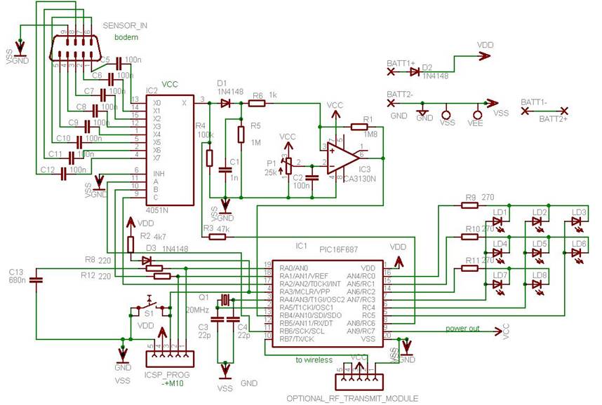
Two lithium batteries are supposed to deliver 6 volts, but in reality this will be about 6. 2 volts with new batteries, the voltage drop over the diode will bring this voltage down to about 5. 7 volts which is acceptable for the PIC and the other chips. So we don`t need to use a voltage regulator IC (which would consume more power). Because measuring fluids with the aid of DC current will lead to electrolytic effects and corrosion problems, in this device we will use a measuring current consisting of an AC block wave with a frequency of about 10 kHz. The circuit`s main purpose is measuring the level in a tank filled with rain water, but of course you can use it for other fluids too.
The circuit uses 8 measuring points that are mounted inside the tank at certain places. By carefully choosing the positions of the electrodes, inaccuracy can be minimized. The microcontroller (IC1) acts as the circuit`s main steering element. Port RC6 (output) is a software oscillator of about 10 kHz. This output pin delivers the measuring current, which is applied to voltage divider R3/R4. By means of the de-multiplexer IC2 en capacitors C5. C12 this measuring current is also applied on the electrodes connected with sub-d connector X1. This happens because the de-multiplexer is controlled by a BCD value (0. 7) provided by the microcontroller on pins, resulting in an alternate scanning of the electrodes. When the electrode being scanned is dry, the measuring voltage is of the same level as provided. When the electrode is under water, an extra load is put on the voltage divider R3/R4 resulting in a somewhat lower voltage. By means of a simple demodulator (D1/C1/R5) the progress of the ac voltage will be converted to some kind of a envelope voltage which is guided to comparator IC3.
The output of comparator IC3 is then guided back into the microcontroller (RB4), a high level meaning the electrode is dry, and a low level meaning the electrode is under water. A side effect of the demodulator is caused by time constant C1/R5, holding the measured value of each electrode until somewhat after the next switchover.
This would mean that the next electrode is measured as under water while in fact it might be dry . We avoid this by waiting half a time block (in terms of RB6). We choose an external 20 MHz crystal as the oscillator because the built-in (max. 8 MHz) oscillator is not fast enough to produce a software frequency of 10 kHz. We need to produce this frequency ourselves in order to have full control during each period (so we cannot use the PIC`s PWM module).
The use of the PIC16F687 as a microcontroller seems like a good choice because this controller embeds some important features which we really need for this project: nanowatt technology, serial communications, I almost always use ICSP programming (in-circuit serial programming) for programming my PICs. You have to realise that this PIC device uses pins RA0 and RA1 for programming and not RB6. RB7 like is the case with most other PICs. Thanks to Fr. Tom McGahee`s I managed to get the serial communications up and running, because he has an excellent website regarding this subject (notice to click on PICUART.
ZIP). I had to make a few changes to his example PICUART source code because of some specific matters on the PIC16F687. The circuit is designed to last at least one year on two lithium button cells. Therefore an on/off switch is obsolete. This is made possible because of the PIC16F687`s built-in so-called Ultra Low Power Wake Up (ULPWU) module.
The microcontroller goes into active mode once an hour during 1. 5 seconds, enough to do the measuring task and send this on RF. After that, the processor will go back to sleep for one hour. During sleep the current consumption is less than 1 µA. During active periods it is about 10 20 mA. The above is implemented like this: a 680 nF capacitor (C13) is connected to pin RA0 (the ULPWU pin). Just before going to sleep the software will do these steps: After this the controller is put into sleep.
During sleep, the current consumption is less than 1 µA. During sleep, the ULPWU module will slowly discharge the capacitor. After 15 seconds the voltage over the capacitor will be dropped below a certain level such that the controller (thanks to the Interrupt-on-change feature) automatically will wake up. Because 15 secs is too short for our goal we maintain a counter (sleepCounter) and go back asleep immediately.
Only after cycling 240 times we reach the one-hour milestone and we decide to do the once-every-hour-work : measuring the fluid and send it on RF. This sending is done a few times (using a counter) to be sure that the receiver has a good reception.
After that we go back to sleep and we are back to square one. Fabricating a suitable sensor is a simple thing to do. Take some flatcable consisting of 9 wires and cut off each wire at the desired length. The ground has to be the longest because ground is coming on the bottom of the tank, or at least below the wire for sensor 1. Strip all 9 ends of the wires about a few millimetres. Next put the flatcable in a piece of PVC tube and fix it. The other side of the flatcable must be soldered on a 9-pin female sub-d connector (ground=pin9, wire 1 =pin1, wire 2=pin2 and so on).
This connector is then plugged onto the male 9-pin (pcb mounted) sub-d connector on the pcb. The below picture shows what you should expect in a correctly built device, when using a 2-channel scope connected to pins RB6 (pin 11 on the PIC) and opamp-out (pin 6 on the CA3130). The green signal is from RB6, the erd signal is from the CA3130 under the condition that sensor wires 1 and 2 are under water.
Time division of the scope is set at 1 ms/div. The more wires that are under water, the wider the red signal`s low-time will be. In the below picture the width of the red signal`s low-time is about 2 green pulses (a green low and a green high). Like mentioned before, the low time of the red signal will expand a little further in time than expected (this is normal) and then it will rise again.
Two other interesting signals to have a look at are the ac voltage on one sensor and the oscillator. Remove the sensor from the water and connect the scope`s channel one to the anode of D1. Connect the scope`s channel 2 to pin 1 of the sub-d connector on the PCB. The scope will now show an ac voltage (the green signal) because of capacitor C5 in between. This AC voltage has 8 periods on sensor one during 1/8 of the time, because the 4051 IC will divide (demultiplex) the oscillator frequency among the 8 sensor wires. The continue oscillator frequency on the anode of D1 (the red signal) is DC voltage because it didn`t pass any capacitor.
Optionally a RF Transmitter module can be mounted on the 5-pin header named OPTIONAL_RF_TRANSMIT_MODULE . As a module I took the TWS-434 RF transmitter module from Rentron ( ). This module is specially made for transmission of serial data on 433. 92 MHz. The same company also has the complementary RWS-434 receiver module. This module receives our data and polishes it back to a nice serial block wave that can be directly read bij the PIC`s USART in the receiver.
The other tasks are doen in the main loop. This includes reading the pushbutton, delay, serial data transmission, automatically go asleep after a minute and so on. The receiver module also contains a PIC16F687 microcontroller as a central element. In addition there are three 7-segment displays. This seems overkill, because one should be enough (measured value is from 0. 8). In the future I plan to use this receiver module for other projects like for example a wireless wind speed meter, hence 3 digits.
The data is received using the RWS-434 RF Receiver module. This module offers its serial data to the PIC on pin 2 (2400 baud). The program is receiving continuously. It might be that you have some other appliances using the same frequency (433. 92 MHz) but this is no problem because the measuring module sends an ID (FLU for Fluid level meter) that is checked in the receiver software. The received data, if valid, is stored in a variable and multiplexed to the display. For the power supply you can use almost any wall adapter delivering a voltage (AC or DC) between 8. 20 V. This voltage is rectified (using diodes D1. D4) and stabilized using a 7805 voltage regulator. Thanks to the rectifier D1. D4 it is impossible to wrongly connect the wall adapter. 🔗 External reference
Place the sensor wires in the t ank. After putting the batteries, you should see the content on the bar-graph display (between 1/8 and 8/8). After about a minute the display will switch itself off. You can switch back on again at any time by shortly pressing the button. To switch back off, press and hold the button for more than 1 second. Once an hour the display will put itself on for a few seconds, while this is happening the device will also transmit the measured value using RF (433.
92 MHz) (optionally). The transmitter/measuring module can be used by itself or in combination with an optional receiver module (wich operates on 230 VAC). This receiver module can be placed in a radius of 30 meter around the transmitter/measuring module. Diode D2 is for protection against reverse polarity of the batteries and also for lowering down the supply voltage somewhat.
Two lithium batteries are supposed to deliver 6 volts, but in reality this will be about 6. 2 volts with new batteries, the voltage drop over the diode will bring this voltage down to about 5. 7 volts which is acceptable for the PIC and the other chips. So we don`t need to use a voltage regulator IC (which would consume more power). Because measuring fluids with the aid of DC current will lead to electrolytic effects and corrosion problems, in this device we will use a measuring current consisting of an AC block wave with a frequency of about 10 kHz. The circuit`s main purpose is measuring the level in a tank filled with rain water, but of course you can use it for other fluids too.
The circuit uses 8 measuring points that are mounted inside the tank at certain places. By carefully choosing the positions of the electrodes, inaccuracy can be minimized. The microcontroller (IC1) acts as the circuit`s main steering element. Port RC6 (output) is a software oscillator of about 10 kHz. This output pin delivers the measuring current, which is applied to voltage divider R3/R4. By means of the de-multiplexer IC2 en capacitors C5. C12 this measuring current is also applied on the electrodes connected with sub-d connector X1. This happens because the de-multiplexer is controlled by a BCD value (0. 7) provided by the microcontroller on pins
The output of comparator IC3 is then guided back into the microcontroller (RB4), a high level meaning the electrode is dry, and a low level meaning the electrode is under water. A side effect of the demodulator is caused by time constant C1/R5, holding the measured value of each electrode until somewhat after the next switchover.
This would mean that the next electrode is measured as under water while in fact it might be dry . We avoid this by waiting half a time block (in terms of RB6). We choose an external 20 MHz crystal as the oscillator because the built-in (max. 8 MHz) oscillator is not fast enough to produce a software frequency of 10 kHz. We need to produce this frequency ourselves in order to have full control during each period (so we cannot use the PIC`s PWM module).
The use of the PIC16F687 as a microcontroller seems like a good choice because this controller embeds some important features which we really need for this project: nanowatt technology, serial communications, I almost always use ICSP programming (in-circuit serial programming) for programming my PICs. You have to realise that this PIC device uses pins RA0 and RA1 for programming and not RB6. RB7 like is the case with most other PICs. Thanks to Fr. Tom McGahee`s I managed to get the serial communications up and running, because he has an excellent website regarding this subject (notice to click on PICUART.
ZIP). I had to make a few changes to his example PICUART source code because of some specific matters on the PIC16F687. The circuit is designed to last at least one year on two lithium button cells. Therefore an on/off switch is obsolete. This is made possible because of the PIC16F687`s built-in so-called Ultra Low Power Wake Up (ULPWU) module.
The microcontroller goes into active mode once an hour during 1. 5 seconds, enough to do the measuring task and send this on RF. After that, the processor will go back to sleep for one hour. During sleep the current consumption is less than 1 µA. During active periods it is about 10 20 mA. The above is implemented like this: a 680 nF capacitor (C13) is connected to pin RA0 (the ULPWU pin). Just before going to sleep the software will do these steps: After this the controller is put into sleep.
During sleep, the current consumption is less than 1 µA. During sleep, the ULPWU module will slowly discharge the capacitor. After 15 seconds the voltage over the capacitor will be dropped below a certain level such that the controller (thanks to the Interrupt-on-change feature) automatically will wake up. Because 15 secs is too short for our goal we maintain a counter (sleepCounter) and go back asleep immediately.
Only after cycling 240 times we reach the one-hour milestone and we decide to do the once-every-hour-work : measuring the fluid and send it on RF. This sending is done a few times (using a counter
After that we go back to sleep and we are back to square one. Fabricating a suitable sensor is a simple thing to do. Take some flatcable consisting of 9 wires and cut off each wire at the desired length. The ground has to be the longest because ground is coming on the bottom of the tank, or at least below the wire for sensor 1. Strip all 9 ends of the wires about a few millimetres. Next put the flatcable in a piece of PVC tube and fix it. The other side of the flatcable must be soldered on a 9-pin female sub-d connector (ground=pin9, wire 1 =pin1, wire 2=pin2 and so on).
This connector is then plugged onto the male 9-pin (pcb mounted) sub-d connector on the pcb. The below picture shows what you should expect in a correctly built device, when using a 2-channel scope connected to pins RB6 (pin 11 on the PIC) and opamp-out (pin 6 on the CA3130). The green signal is from RB6, the erd signal is from the CA3130 under the condition that sensor wires 1 and 2 are under water.
Time division of the scope is set at 1 ms/div. The more wires that are under water, the wider the red signal`s low-time will be. In the below picture the width of the red signal`s low-time is about 2 green pulses (a green low and a green high). Like mentioned before, the low time of the red signal will expand a little further in time than expected (this is normal) and then it will rise again.
Two other interesting signals to have a look at are the ac voltage on one sensor and the oscillator. Remove the sensor from the water and connect the scope`s channel one to the anode of D1. Connect the scope`s channel 2 to pin 1 of the sub-d connector on the PCB. The scope will now show an ac voltage (the green signal) because of capacitor C5 in between. This AC voltage has 8 periods on sensor one during 1/8 of the time, because the 4051 IC will divide (demultiplex) the oscillator frequency among the 8 sensor wires. The continue oscillator frequency on the anode of D1 (the red signal) is DC voltage because it didn`t pass any capacitor.
Optionally a RF Transmitter module can be mounted on the 5-pin header named OPTIONAL_RF_TRANSMIT_MODULE . As a module I took the TWS-434 RF transmitter module from Rentron ( ). This module is specially made for transmission of serial data on 433. 92 MHz. The same company also has the complementary RWS-434 receiver module. This module receives our data and polishes it back to a nice serial block wave that can be directly read bij the PIC`s USART in the receiver.
The other tasks are doen in the main loop. This includes reading the pushbutton, delay, serial data transmission, automatically go asleep after a minute and so on. The receiver module also contains a PIC16F687 microcontroller as a central element. In addition there are three 7-segment displays. This seems overkill, because one should be enough (measured value is from 0. 8). In the future I plan to use this receiver module for other projects like for example a wireless wind speed meter, hence 3 digits.
The data is received using the RWS-434 RF Receiver module. This module offers its serial data to the PIC on pin 2 (2400 baud). The program is receiving continuously. It might be that you have some other appliances using the same frequency (433. 92 MHz) but this is no problem because the measuring module sends an ID (FLU for Fluid level meter) that is checked in the receiver software. The received data, if valid, is stored in a variable and multiplexed to the display. For the power supply you can use almost any wall adapter delivering a voltage (AC or DC) between 8. 20 V. This voltage is rectified (using diodes D1. D4) and stabilized using a 7805 voltage regulator. Thanks to the rectifier D1. D4 it is impossible to wrongly connect the wall adapter. 🔗 External reference