
Regulated-driven-converter
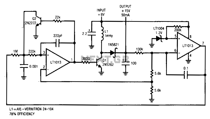
This converter delivers up to 50 mA from a 6-V battery with 78% efficiency. This flyback converter functions by feedback-controlling the frequency of inductive flyback events. The inductor's output is rectified and filtered to de-bias the feedback loop to establish a stable output. If the converter's output is below the loop setpoint, A2's inputs unbalance, and current is fed through the 1-MΩ resistor at A1. This ramps the 1000-pF capacitor positively. When this ramp exceeds the 0.5-V potential at A1's positive input, the amplifier switches high.
Q2 turns on, discharging the capacitor to ground. Simultaneously, regenerative feedback through the 200-pF capacitor causes a positive-going pulse at A1's positive input, sustaining A1's positive output. Q1 turns on, allowing inductor L1 current to flow. When A1's feedback pulse decays, its output becomes low, turning off Q1. Q1's collector is pulled high by the inductor's flyback, and the energy is stored in the 100-µF capacitor. The capacitor's voltage, which is the circuit output, is sampled by A2 to close a loop around A1/Q1. This loop forces A1 to oscillate at whatever frequency is required to maintain the 15-V output. In-phase transformer windings for the drain and gate of the TMOS power FET Q1 cause the circuit to oscillate. Oscillation starts when the feedback coupling capacitor, C1, is charged from the supply line via a large resistance; R2 and R3 limit the collector current to Q2. During pump-up, the on time is terminated by Q2, which senses the ramped source current of Q1. C1 is charged on alternate half-cycles by Q2 and forward-biased by zener D2. When the regulated level is reached, forward bias is applied to Q2, terminating the on time earlier at a lower peak current. When this occurs, the frequency increases in inverse proportion to current, but the energy per cycle decreases in proportion to current squared. Therefore, the total power coupled through the transformer to the secondary is decreased.
The described flyback converter is a compact and efficient power supply solution that converts a 6-V input from a battery into a regulated 15-V output while maintaining an efficiency of 78%. The operation of the converter is fundamentally based on the principles of inductive energy storage and feedback control.
The converter employs a feedback mechanism where the output voltage is monitored and compared against a setpoint. The operational amplifier A1 plays a crucial role in regulating the output voltage by adjusting the frequency of the switching events. When the output voltage drops below the desired level, A1 generates a ramp signal that triggers the switching of Q2. This switching action discharges the capacitor, allowing for the rapid transfer of energy from the inductor L1 to the output capacitor, which smooths the output voltage.
The circuit utilizes a combination of capacitors and resistors to shape the feedback signals and control the timing of the switching events. The feedback coupling capacitor C1 is essential for initiating the oscillation of the converter. The resistors R2 and R3 are strategically placed to limit the current to the switching transistor Q2, preventing damage and ensuring stable operation.
The use of a zener diode D2 provides additional regulation by forward-biasing Q2 at the appropriate voltage levels, further stabilizing the output. The transformer is designed with in-phase windings for the gate and drain of Q1, which enhances the efficiency of the energy transfer process.
Ultimately, the flyback converter's ability to vary its switching frequency in response to load conditions allows it to maintain a consistent output voltage while adapting to changes in input voltage and load demands. This characteristic makes it suitable for a wide range of applications where reliable power conversion is required.This converter delivers up to 50 mA from a 6-V battery with 78% efficiency. This flyback converter functions by feedback-controlling the frequency of inductive flyback events. The inductor"s output, rectified and filtered to de, biases the feedback loop to establish a stable output. If the converter"s output is below the loop setpoint, A2"s inputs unbalance and current is fed through the 1-MO resistor at Al.
This ramps the 1000-pF value positive. When this ramp exceeds the 0.5-V potential at A1 "s positive input, the amplifier switches high. Q2 turns on, discharging the capacitor to ground. Simultaneously, regenerative feedback through the 200-pF value causes a positive-going pulse at A1"s positive input, sustainlljg A1"s positive output. Q1 comes on, allowing inductor, 11, current to flow. When A1"s feedback pulse decays, its output becomes low, turning off Ql. Q1"s collector is pulled high by the inductor"s flyback and the energy is stored in the 100-I"F capacitor.
The capacitor"s voltage, which is the circuit output, is sampled by A2 to close a loop around Al/Ql. This loop forces A1 to oscillate at whatever frequency is required to maintain the 15-V output. In-phase transformer windings for the drain and gate of TMOS power FET Q1 cause the circuit to oscillate.
Oscillation starts when the feedback coupling capacitor, C1, is charged from the supply line via a large resistance; R2 and R3 limit the collector current to Q2. During pump-up, the on time is terminated by Q2, which senses the ramped source current of Ql. C1 is charged on alternate half-cycles by Q2 and forward-biased by zener D2. When the regulated level is reached, forward bias is applied to Q2, terminating the on time earlier at a lower peak current.
When this occurs, the frequency increases in inverse proportion to current, but the energy per cycle decreases in proportion to current squared. Therefore, the total power coupled through the transformer to the secondary is decreased. 🔗 External reference