
Regulator-current-source
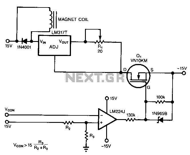
The circuit powers the load through the input of the regulator rather than its output. Due to the presence of a constant dummy load (R1) at the regulator's output, it attempts to draw a constant amount of current, regardless of the voltage across the actual load. Thus, the regulator's input functions as a constant-current source for the actual load. The circuit can be powered using any commonly available ±15V or ±12V supplies. The voltage drop across the regulator and dummy load reduces the total compliance voltage of the circuit. The load's current is set using Rl, where the current is equal to 1.25 A divided by Rl.
The described circuit operates by utilizing a voltage regulator configured to provide a stable current output to the load, while the regulator's input is directly connected to a power supply. The choice of commonly available power supplies, such as ±15V or ±12V, allows for flexibility in various applications. The dummy load, represented by resistor R1, is critical in ensuring that the regulator maintains a consistent output current, effectively isolating the load from variations in voltage.
The current through the load can be precisely controlled by adjusting the value of Rl, which serves as a sensing resistor. The relationship defined by the equation \( I = \frac{1.25 \, \text{A}}{R_l} \) indicates that increasing the resistance of Rl will reduce the output current, while decreasing Rl will increase the current delivered to the load. This feature is particularly useful in applications where specific current levels are required for optimal performance.
Additionally, the voltage drop across the regulator and the dummy load is a critical consideration in the design, as it affects the overall compliance voltage available to the load. The effective voltage supplied to the load is the input voltage minus the voltage drop across the regulator and the dummy load. Therefore, careful selection of the regulator and dummy load values is essential to ensure that the load receives sufficient voltage for its operation while maintaining the desired current output.
Overall, this circuit design is advantageous for applications requiring a stable current source, allowing for precise control over the load's operational parameters. Proper implementation of the components and careful consideration of the voltage drops will enable efficient and reliable circuit performance.The circuit powers the load via the regulator"s input instead of its output. Because the regulator"s output sees constant dummy load R1, it tries to consume a constant amount of current, no matter what the voltage across the actual load really is. Hence, the regulator"s input serves as a constant-current source for the actual load. Power the circuit with any one of the commonly available ± 15 or ±12 V supplies. The voltage dropped across the regulator and dummy load decreased the total compliance voltage of the~circuit. You set the load"s current with Rl. The current equals 1.25 A/"J x Rl. 🔗 External reference