
Relay control circuit
The motor winding described operates in a delta configuration, which allows for efficient power distribution and improved performance in three-phase systems. The delta transposition capacitance, labeled as cl-C-3G, plays a crucial role in managing the capacitive characteristics of the motor, enhancing its operational stability and responsiveness.
The system includes a DC LAN speed generator that works in conjunction with the three-phase asynchronous motor. This motor type is favored for its simplicity and robustness, making it suitable for various industrial applications. The coaxial connection of the field winding ensures that the motor can effectively utilize the 10V power supply, facilitating smooth operation.
The RP (Regulating Processor) connects to the network through the T-ST input terminal, serving as a critical component for speed feedback. This configuration allows for real-time adjustments to the motor's speed, ensuring optimal performance under varying load conditions. The negative feedback loop is essential for maintaining the desired operational parameters and enhancing the overall efficiency of the system.
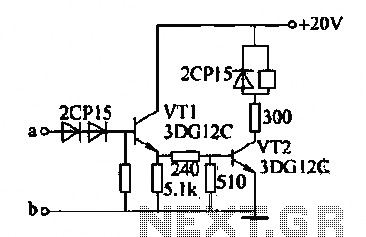
The relay control circuit, identified as 2140, provides a mechanism for controlling the motor's operation. It includes a two-stage amplification process that enables the relay K to engage effectively. The contacts of relay K, both normally open and normally closed, are integral to the control system's indicators, allowing for visual feedback on the system's status. Additionally, the relay aids in managing the WT capacitance island ring, which is essential for the stabilization and regulation of the motor's performance.
In summary, the described system integrates advanced motor winding techniques with effective control mechanisms, ensuring reliable operation and adaptability in various applications. The interplay between the motor, feedback systems, and control circuits exemplifies the complexities of modern electrical engineering in motor control applications.Motor winding is delta transposition capacitance cl -C -3G DC Lan speed generator and three-phase asynchronous motor coaxial cs mechanically connected by a field winding powered disabilities 10V. RP connected to the network via T-ST input terminal, providing speed negative feedback. 8) relay control circuit: 2140 as shown in FIG. After the two-stage amplification relay K pull, use K normally open and normally closed contacts are control system indicators and short WT capacitance island ring, ring become so WT P mediators.
Related Circuits
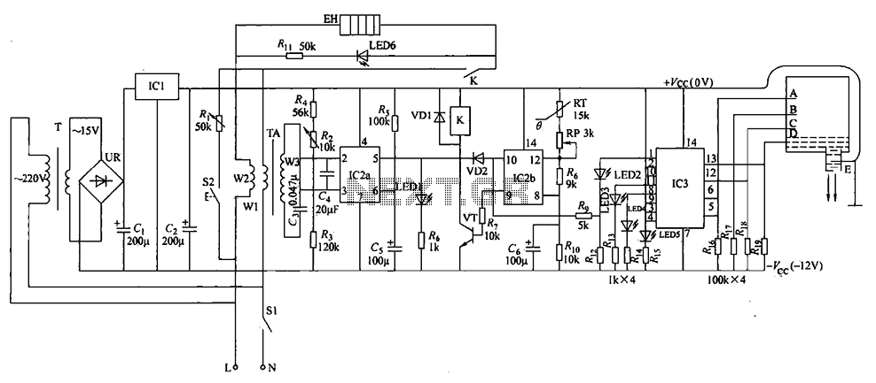
The electric water heater temperature control circuit includes functions for water level indication, temperature regulation, anti-dry protection, and automatic leakage power protection, ensuring safety and reliability. The circuit consists of a power circuit, leakage protection circuit, temperature control circuit,...
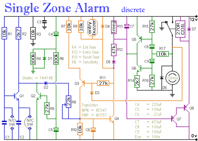
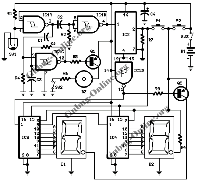
The circuit includes automatic entry and exit delays, a timed bell cut-off, and a system reset feature. It accommodates both normally open and normally closed switches, making it compatible with common input devices such as pressure mats, magnetic reed...
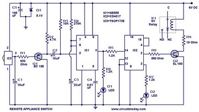
555 Timer TV Remote Controlled Home Appliance Circuit Diagram. Features: 555 timer IC to avoid fast switching. You can only switch the circuit. The 555 timer integrated circuit (IC) is a versatile component widely used in various electronic applications, including...
This lie detector circuit diagram provides two readings: one for challenging questions directed at the subject and another to display the subject's emotional state in general. The emotional states are detected not only by heart rate variations and perspiration...
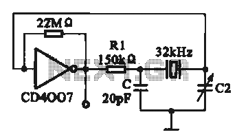
A 32 kHz clock oscillator is essential for digital circuits, as depicted in the schematic. The 32 kHz crystal clock oscillator serves to provide a time reference signal for the digital circuit. It utilizes a CMOS integrated circuit, specifically...
This circuit design is intended for conducting harmless experiments with high-voltage pulses, functioning similarly to an electrified fence generator. The pulse repetition frequency (PRF) is determined by the time constant of the resistor-capacitor network R1-C3 in the feedback loop...