
Relay Driver Circuit
Diodes are essential in relay circuits, serving to suppress voltage spikes that occur when the relay opens and closes. The coil of a relay acts as an inductor, which inherently resists changes in current. When current flow is abruptly interrupted, such as when a switch opens, the coil generates a sudden, high voltage spike due to the collapsing magnetic field. This phenomenon can be mathematically expressed as V=L(dI/dt), where a rapid change in current results in a significant voltage across the coil. Such voltage spikes can reach levels as high as 1000V, potentially damaging nearby electronic components, including switches and transistors, as well as the relay's switch contacts.
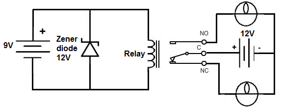
To mitigate these voltage spikes in DC relay circuits, a diode is placed in reverse bias across the relay coil. This configuration allows the diode to conduct before excessive voltage can develop across the coil, effectively shunting the current to ground and protecting the relay and other components from damage. The diode must be rated to handle currents equivalent to the maximum current that would flow through the coil during normal operation. For example, if a relay is rated for 9V, a 9-volt DC power source will be used to supply the relay. To further suppress transients, a zener diode may also be utilized in reverse bias in parallel with the relay, shunting excess power to ground.
In contrast, AC relays cannot employ a diode for voltage spike suppression due to the alternating nature of AC current. Instead, an RC series network is placed across the coil in parallel to create an effective transient voltage suppressor. The capacitor absorbs excess charge, while the resistor controls the discharge rate. Caution is advised when working with AC power from wall outlets due to the risk of electric shock; professional consultation is recommended before interfacing with mains voltage.
For an AC relay rated at 110VAC, it is necessary to supply it with 110V from an AC power source. The RC network serves to suppress voltage spikes, allowing the relay to operate and power connected loads. This relay driver circuit can be powered by either AC or DC input voltage. Unlike other circuits, this design does not require a specific rated voltage, as the presence of a transistor allows for reduced power consumption on the input side.
The transistor functions as an amplifier, requiring sufficient current at its base terminal to enable larger current flow from the emitter to the collector. When adequate voltage and input current are applied to the base, the transistor conducts and powers the relay. Conversely, without voltage or current at the base, the transistor remains off, blocking current flow through the relay coil. This design effectively allows for the efficient control of the relay while minimizing power requirements.In this project, we will build a relay driver for both DC and AC relays. Since DC and AC voltages operate differently, to build relay drivers for them requires slightly different setup. We will also go over a generic relay driver which can operate from either AC or DC voltage and operate both AC and DC relays.
All relays come with a voltage rating . This is called on a relay`s datasheet its rated coil voltage. This is the voltage needed in order for the relay to be able to operate and be able to open or close its switch in a circuit. In order for a relay to function, it must receive this voltage at its coil terminals. Thus, if a relay has a rated voltage of 9VDC, it must receive 9 volts of DC voltage to operate. So the most important thing a DC relay needs is its rated DC voltage. If you don`t know this, look up what relay you have and look up its datasheet and check for this specification.
And the reason why a diode is needed is usually because it functions to eliminate voltage spikes from a relay circuit as the relay opens and closes. The coil of a relay acts an inductor. Remember that inductors are basically coils of wires wrapped around a conductive core. This is what relay coils are as well. Therefore, they act as inductors. Inductors are electronic components that resist changes in current. Inductors do not like sudden changes in current. If the flow of current through a coil is suddenly interrupted, for example, a switch opening, the coil will respond by producing a sudden, very large voltage across its leads, causing a large surge of current through it.
From a physics or physical perspective, this phenomen is a result of a collapsing magnetic field within the coil as the current is terminated abruptly. Mathematically, this can be understood by noticing how a large change in current (dI/dt) affects the voltage across a coil (V=LdI/dt).
Since we are opening the switch, in this case, the current literally goes from full mode to 0 instantaneously. This creates a large voltage spike. Surges in current that result from inductive effects can create very high voltage spikes (as high as 1000V) that can have nasty effects on neighboring devices with in the circuits, such as switches and transistors getting zapped.
Not only are these voltage spikes damaging to other electronic components in a circuit but thye are also damaging to the relay`s switch contacts. The contacts will suffer from these spikes as well. So how do we prevent these voltage spikes How can we suppress them so that they don`t cause this damage The answer for DC relay circuits is to use a diode.
A diode is placed reverse biased in parallel with the relay. The diode acts as a transient suppressor. A transient is a spike. A transient suppressor suppresses these spikes. Placing a diode in reverse bias across a relay`s coil eliminates voltage spikes by going into conduction before a large voltage can form across the coil. In other words, a diode will conduct current in reverse bias once the voltage reaches a certain threshold and shunt the current to ground.
Once the diode begins conducting, it no longer holds voltage. So that the relay in parallel will not receive the excess voltage. So the diode functions to shunt excess power to ground once it reaches a certain threshold. Diodes are devices that do not conduct in reverse. However, if the voltage reaches a certain level, called the breakdown voltage, it will conduct. This is a good thing, when we need the diode to act as a transient suppressor, because it forces all excess power to ground, as to not affect any other parts of the circuit. The diode must be rated to handle currents equivalent to the maximum current that woudl have been flowing through the coil before the supply current was interrupted.
Therefore, if the relay normally passes a certain amount of current through it during normal operation, the diode must be rated for a current rating above this value, as to not stop normal operation. The relay which we use in this case is rated for 9V. Therefore, a 9-volt DC voltage source feeds the resistor. To suppress transients that may be caused by the relay opening and closing, we place a zener diode reverse biased in parallel with the relay.
This will shunt all excess power to ground once it reaches a certain threshold. This is all that is needed to operate the relay. With sufficient power, the relay will now closed, driving the loads that are connected to its output. Unlike DC relays, however, you cannot use a diode to to eliminate voltage spikes. With AC power, the diode will conduct on alternate half-cycles. Using 2 diodes in reverse parallel will also not work because the current will not make it to the coil of the relay.
The current will just go through the diodes. Instead, to create a working transient voltage suppressor with an AC circuit, we use an RC series newtwork placed across the coil in parallel. The capacitor absorbs excessive charge and the resistor helps to control the discharge. Warning: Be very careful with AC power coming directly from a wall outlet because it is lethal enough to cause shock.
Please consult a professional before taking power directly from a plug in a wall outlet. We, again, feed the AC relay the AC voltage it is rated for. If we use a relay with a rated voltage of 110VAC, we must feed it 110V from an AC power source. The capacitor and resistor in series acts as the transient voltage suppressor to suppress voltage spikes. This first half of the circuit serves as the relay driver. With the relay now having sufficient power, it will turn on and power the loads it is connected to. This is a relay driver circuit which can be driven by either AC or DC input voltage. And unlike the other circuits, a specific voltage, such as the rated voltage values we used to drive the others, does not need to be used.
Because this circuit contains a transistor, much less power needs to used on the input side to drive it. Now that we`re using a transistor to drive the relay, we can use considerably less power to get the relay driven.
Because a transistor is an amplifier, we just have to make sure that the base lead gets enough current to cause a larger current to flow from the emitter of the transistor to the collector. Once the base receives sufficient power, the transistor will conduct from emitter to collector and power the relay.
With no voltage or input current applied to the transistor`s base lead, the transistor`s emitter-to-collector channel is open, hence blocking current flow through the relay`s coil. However, if sufficient voltage and input current are applied to the base lead, the transistor`s emitter-to-collector channel will open, allowing current to flow through the relay`s coil.
🔗 External reference
Related Circuits
This circuit was built to charge two series lithium cells (3.6 volts each, 1 Amp Hour capacity) installed in a portable transistor radio. The circuit is designed to efficiently charge two lithium-ion cells connected in series. Each cell has a...
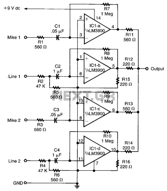
Designed around an LM3900 quad op amp, this mixer combines two line inputs and two microphone inputs, summing them at the output terminal. Resistors R7 through R10 can be adjusted to vary the gain, approximately +23 dB. The mixer circuit...
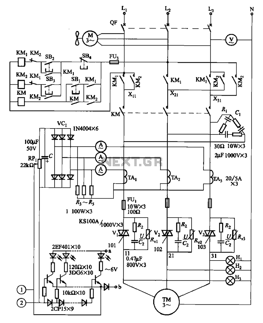
The circuit illustrated in Figure 3-178 is designed for controlling the speed and torque of a motor used in a continuous casting machine. It consists of the main circuit, a trigger circuit, and both manual and automatic control signal...
The following circuit illustrates a Bass-Treble Tone Control Circuit electronic diagram based on the LM1035N integrated circuit (IC). Features include a 0.3 Vrms input level, 80 dB signal noise ratio, 75 dB volume control, ±15 dB typical tone control,...
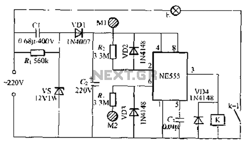
A use NF double touch lamp circuit based on a 55 base design, utilizing switches. It operates with 220V AC and includes a simple composition of a power-saving buck converter in conjunction with a half-bridge circuit. The circuit is...
This circuit will allow you to connect any tape recorder that has a mic and remote input to a phone line and automatically record both sides of a conversation whenever the phone is in use. You will need to...
Warning: include(partials/cookie-banner.php): Failed to open stream: Permission denied in /var/www/html/nextgr/view-circuit.php on line 713
Warning: include(): Failed opening 'partials/cookie-banner.php' for inclusion (include_path='.:/usr/share/php') in /var/www/html/nextgr/view-circuit.php on line 713