
relay found in switch mode power supply

The described circuit utilizes a low-voltage control mechanism to operate a high-voltage load safely. The relay serves as an isolating switch, ensuring that the low-voltage control circuit does not come into direct contact with the high-voltage AC circuit, thus providing safety and preventing potential hazards.
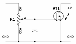
In this configuration, the transistor Q1 acts as a switch that controls the relay coil. When the base of Q1 receives a sufficient voltage, it allows current to flow from the 12V rail through the relay coil, energizing it. This energization creates a magnetic field that moves the relay's armature, closing the contacts and allowing current to flow through the 240V AC circuit.
The role of the microprocessor in the television is crucial, as it initiates the relay operation by sending a brief activation signal to Q973, which in turn controls the relay coil. This sequence ensures that the degaussing coil is activated only during the initial power-up phase, helping to eliminate any unwanted magnetic distortions on the screen.
Testing procedures for both the relay coil and contacts are essential for maintenance. The diode test on the coil checks for continuity, confirming that the coil has not burned out. The contact test ensures that the relay can effectively switch the AC load on and off, which is critical for the reliable operation of the entire circuit. This combination of components and testing methods provides a robust solution for controlling high-voltage devices using low-voltage control signals.In the example above a low voltage (12Vdc) is used to turn on a relay to switch on a 240V ac main circuit. Please note that there is no electrical connection inside the relay between the two circuits, the link is only magnetic and mechanical.
If there is Zero (0) volt at the Base (B) of transistor Q1. The transistor is open and therefore current is not able to flow from the 12V rail to the Ground and hence the relay contacts are open and the 240V ac Bulb is off. Now if a Voltage is applied at the Base (B) of transistor Q1. The transistor will close(ON) and the current will start flowing from the 12V rail through the relay coil to the Collector of the Q1 down to the Ground. When the current flow through the coil a magnetic field is created around the wire and this magnet (electro) will attract the contacts of the relay.
Once the contacts closes then the other circuit is switched on and the Bulb light. When the Television is first switched on a signal is send from the TV micro processor to the base of Q973 just for a moment (2 seconds). When this signal reaches the base of transistor Q973 the transistor is turned ON and the 12 Volts DC moves to the ground via relay coil.
When current flow through the relay coil it behaves like a magnet and relay switch (contacts) is closed. When the relay switch is closed the current flow through the relay on the 240V ac into the Degaussing Coil and the screen is cleaned.
Coil: Use your meter set to diode test and you should get a reading if the coil is okay. If no reading then the coil is open and therefore the relay is bad. Contacts: To test if the contacts are working you need to apply some Voltage (5V dc) to the two pins of the coil and if the contact is working then you should hear a click sound from the relay. 🔗 External reference
Related Circuits
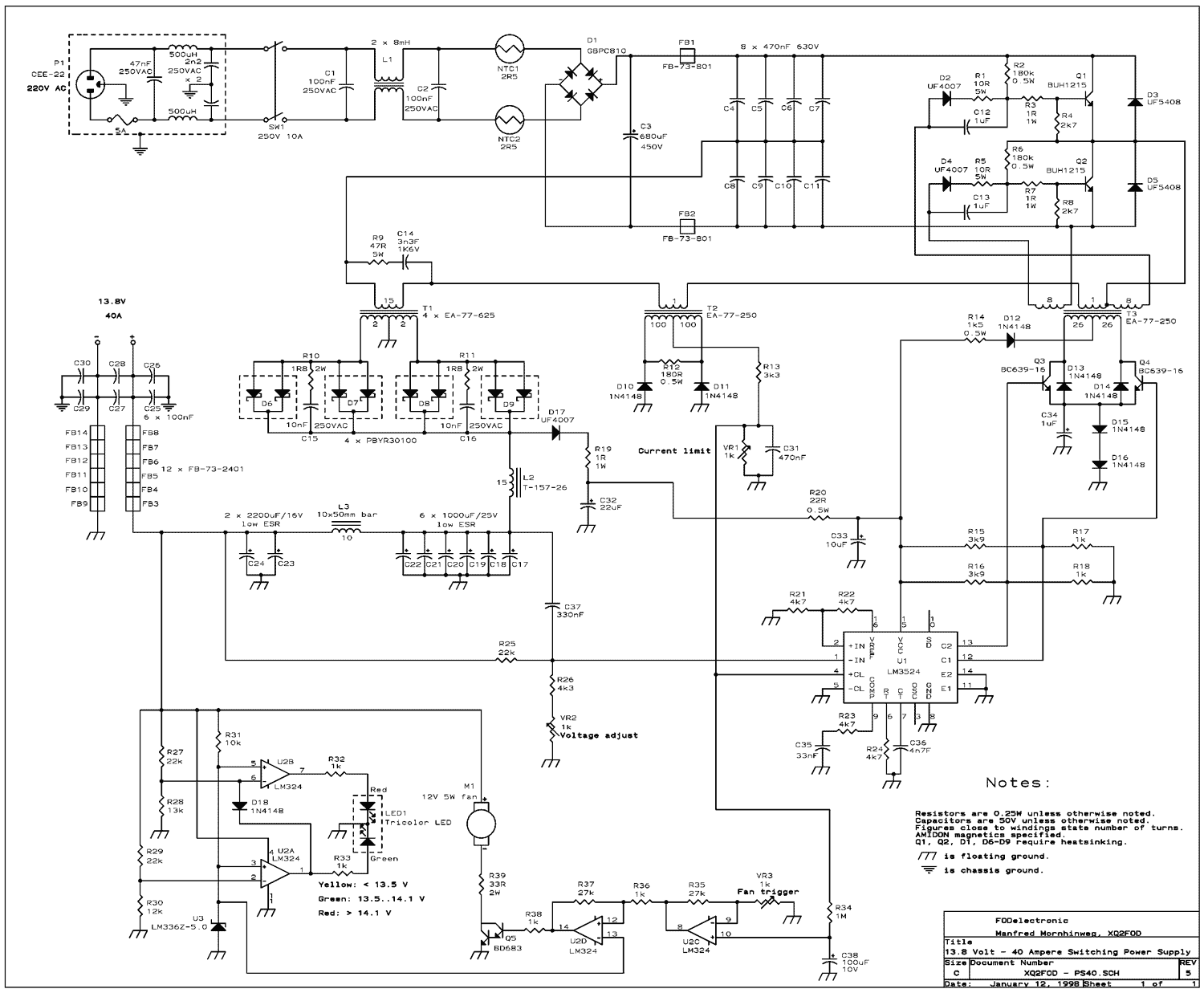
The present trend is to use ever higher frequencies. But by doing so it becomes more difficult to filter out the RF noise inevitably generated by the switching. So I decided to stay at a low switching frequency of...
This regulated power supply can be adjusted from 3 to 25 volts and is current limited to 2 amps as shown, but may be increased to 3 amps or more by selecting a smaller current sense resistor (0.3 ohm)....
This article provides a comprehensive overview of the methodology used for testing power supplies (PSUs) in three main sections. The first section outlines the PSU parameters that are evaluated and specifies the testing conditions. The second section defines commonly...
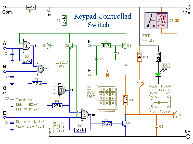
This is a universal version of the four-digit alarm control keypad. The design has been modified to free up the relay contacts, allowing the circuit to function as a general-purpose switch. A single pole changeover (SPCO) or single pole...
Electronic ballasts for dimming fluorescent lamps require a control interface for the user to set the desired lamp brightness level. Existing interface circuits include a 1-to-10 Vdc interface, a digitally-addressable lighting interface (DALI), triac-based wall dimmers, three-way lamp sockets,...
This circuit is constructed around a 555 timer and utilizes very few components. Due to its simplicity, even beginners can easily assemble and use it as a control device. A readily available laser pointer can be employed to operate...