
remote controlled dc motor circuit

The described circuit serves as an introductory project for individuals interested in electronics and remote control systems. The TSOP IR receiver is a critical component, designed to detect infrared signals emitted from a remote control. The circuit's simplicity makes it an excellent choice for beginners aiming to understand the fundamentals of remote control technology and motor operation.
In this circuit, the TSOP IR receiver is connected to a microcontroller or a simple transistor switch that controls the DC motor. The DC motor is powered by a regulated 5V supply, which is essential for the proper functioning of the TSOP IR receiver. The operation of the circuit can be explained through a few key points:
1. **Power Supply**: A stable 5V power supply is necessary to ensure that the TSOP operates correctly. This voltage is also used to power the DC motor.
2. **IR Signal Reception**: The TSOP receives infrared signals from a remote control. When a button is pressed on the remote, it transmits a specific IR code, which the TSOP detects.
3. **Output Control**: Upon receiving the IR signal, the TSOP changes its output state. If the signal indicates to start the motor, the output goes high (5V), activating the transistor or microcontroller to power the DC motor. Conversely, when the signal indicates to stop, the output returns to low (0V), deactivating the motor.
4. **Timing Circuit**: The timing aspect of the circuit is determined by the RC time constant (T=1.1RC). This defines how long the output remains high after the TSOP detects an IR signal. The values of the resistors and capacitors in the timing circuit will dictate the duration for which the motor remains active.
5. **Limitations**: As previously noted, this circuit does not allow for speed control of the motor. The motor runs at a fixed speed once activated. For projects requiring variable speed control, the implementation of a PWM (Pulse Width Modulation) controller would be necessary, which is indicated as a future enhancement.
This hobby circuit provides a foundational understanding of remote control operation and motor control, making it an ideal project for those beginning their journey in electronics.This is a simple hobby circuit of a remote controlled toy car. The main component used here is the IR sensor circuit consisting of TSOP. Using a TSOP IR receiver we can start and stop the DC motor vehicle. However this circuit has a small disadvantage that it can`t control the speed of DC car motor, rather it ON and OFF the small dc motors. Thus i t is suitable for electronics beginners only. Once it is ON, the motor runs with a constant speed. No speed control circuits are discussed here. The advanced version of this circuit with PWM speed controller will be posted soon. You must need a regulated power supply of 5 volt to do this one because TSOP requires 5v for its operation. Below is the circuit diagram and working of remote controlled dc motor for car using T sop infrared detector circuit.
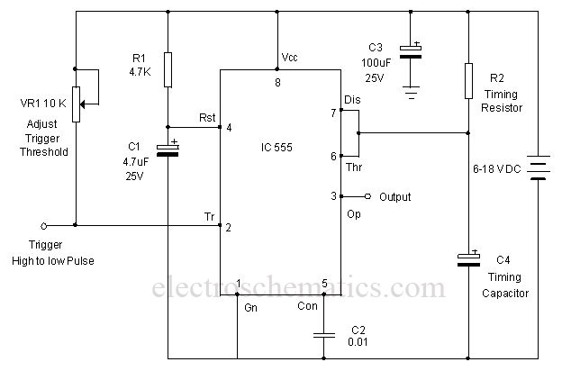
When the voltage at the 2nd pin goes below 1/3Vcc, output switches to high (5V) for the time interval T=1. 1RC. After this time interval output returns to 0V. 🔗 External reference
Related Circuits
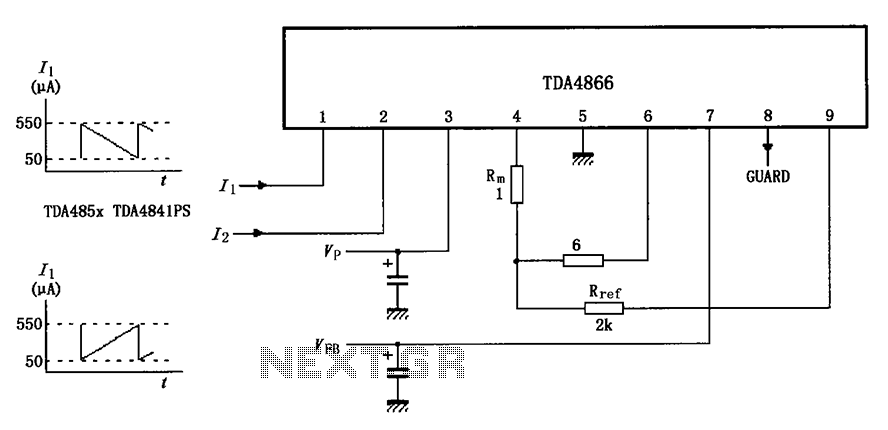
The TDA4866 test circuit operates with a positive supply voltage (VP) and a feedback voltage (VFB) in conjunction with a flyback circuit. The circuit responds to changes in the input signal, transitioning from one state to another. The input...

The objective of the circuit is to create an electronic dice using the functionality of a 555 timer integrated circuit operating in astable mode. The electronic dice circuit utilizes a 555 timer configured in astable mode to generate a series...
A monostable multivibrator using the IC CD4538 is a precision device that functions as a monostable/astable multivibrator and is designed to avoid false triggering. This IC is suitable for various applications requiring precise timing cycles. The CD4538 offers improved...
U1 is a 3817 integrated circuit produced by Fairchild Corporation. It is capable of directly driving a display and can operate in both 12-hour and 24-hour formats. Additionally, it can generate a clock sound and activate radios at scheduled...
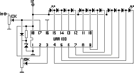
The NL3ASD schematic pages provide the schematics for a LED VU meter utilizing the UAA180 integrated circuit. The NL3ASD schematic pages feature a comprehensive design for a LED VU meter that employs the UAA180 IC, known for its audio signal...
This is a simple tool designed to measure the level of radiation emitted by electrical or electronic devices. The circuit utilizes LEDs to create a running light pattern when it detects electromagnetic radiation from a source. It can detect...
Warning: include(partials/cookie-banner.php): Failed to open stream: Permission denied in /var/www/html/nextgr/view-circuit.php on line 713
Warning: include(): Failed opening 'partials/cookie-banner.php' for inclusion (include_path='.:/usr/share/php') in /var/www/html/nextgr/view-circuit.php on line 713