
Remote-controlled preamplifier
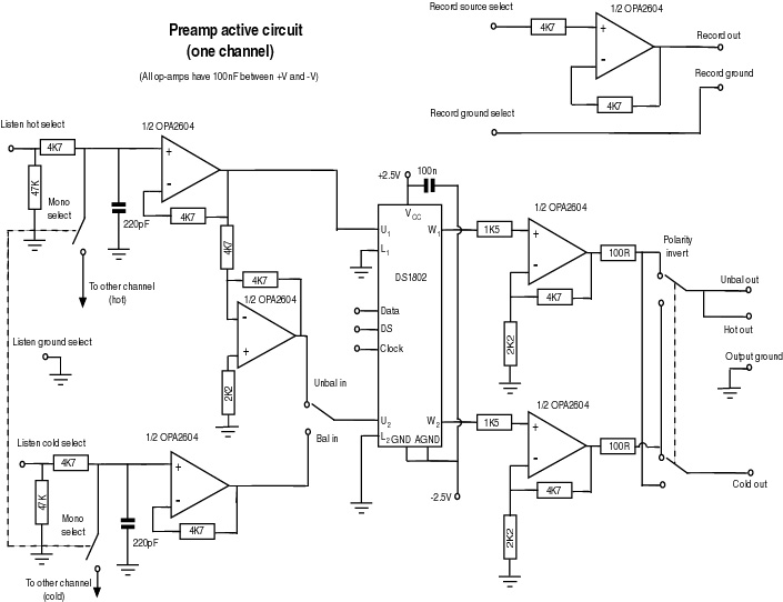
The circuit design focuses on creating a high-fidelity audio preamplifier with an emphasis on minimizing noise and distortion. The use of Burr-Brown OPA2604 op-amps is notable for their low noise characteristics and high-performance audio applications. The output stage, with a gain of +10dB, is configured to ensure adequate signal levels for subsequent amplification stages while maintaining low distortion. The design incorporates a first-order low-pass filter to limit the bandwidth, effectively reducing the susceptibility to radio frequency interference (RFI) and ensuring that high-frequency noise does not compromise audio quality.
The choice of sealed relays with gold-plated contacts is critical for maintaining signal integrity during switching operations. By utilizing separate power supplies for relays and logic circuits, the design effectively isolates digital noise from sensitive analog signals, thus enhancing overall performance.
The decision to implement a digital volume control using the DS1802 introduces flexibility and precision in volume adjustment, which is particularly beneficial in high-end audio applications. The digital potentiometer's integration into the circuit allows for more refined control over the audio signal, although considerations regarding its audio fidelity compared to traditional mechanical potentiometers remain.
Overall, the circuit is designed with a clear focus on achieving high performance while allowing for future enhancements and modifications through the planned transition to a more permanent PCB layout. The ongoing construction and testing phases will provide valuable insights into the design's effectiveness, guiding further refinements and optimizations.This is a distillation of my " design notes ", with more practical details as I move along with the construction, and (in due course) some pictures. Right at the moment I`m using it as a kind of progress report for myself - it`s a mixture of immediate plans and actual construction, so isn`t too clearly structured!
The signal control circuit is on 0. 1" matrix board for the time being - after hours of trying to work out exactly what was going to go where on a PCB, I decided to start soldering everything together anyway to make a prototype. Right now the board is getting pretty crowded, and there isn`t room for all the traces. For the moment I want to keep one or two options open, for instance the volume control and the layout of the balanced connections.
At some point in the not-too distant future, though, I hope I`ll be more or less satisfied with what I`ve got, and then I`ll build a proper set of PCBs for the project, which will be a chance to tidy it all up, and of course add such niceties as a ground plane if I can. I use sealed relays with gold-plated silver contacts, type 53W/1 from Fujitsu, for all switching, including output polarity and mono/stereo selection.
The 5V power supply for the relays is separately regulated from the ones for the TTL logic and the indicator LEDs to avoid glitches. All op-amps are Burr-Brown OPA2604, with one pair of LM317/337 regulators for each stereo channel. The gain of the output stage is +10dB, while the input buffers are unity gain except for the CD input (see below).
If an unbalanced input is selected, the balanced signal is generated by inverting the input before the volume control, so that antiphase signals are always present in the volume control and output stages - this ought to decrease hum and RF pickup and improve the power supply rejection ratio. The only drawback of this is that is means that if I wanted to use a mechanical potentiometer for the volume control, instead of the digital one currently installed, I would need either to find a quad ganged one, or to reconfigure the balanced output.
There is a first-order low-pass filter at the inputs, with a pole at around 300kHz, to define the bandwidth of the amp, and to reduce the ingress of high frequency noise. I`ve had trouble with RF demodulation with one or two circuits before, and this filtering (together with the copper foil shielding inside the boxes) should help.
The digital volume control I use (see below) has a quoted 3dB bandwidth of 700kHz, so I wanted to keep the net bandwidth of the preamplifier within this too. I`m intending to build a couple of wide bandwidth power amps shortly to add to this system, and I want to minimise the risk of frying my tweeters.
The matrix board isn`t quite big enough for some of the control functions (the optoisolators, for instance), so these have been relocated to the digital board for the moment. After lengthy consideration - see my notes - I decided that the most logical and practical (though not necessarily the ideal in subjective terms!) solution for volume control was to use a digital potentiometer.
As an initial trial, I settled on the Dallas Semiconductor DS1802 stereo digital potentiometer (partly because it allows push-button input as well as the serial connection, but mostly because Maplin stock it and it`s cheap). I use one chip for each channel, and one channel of each chip handles each of the two polarities of the balanced signal outputs.
The DS digital potentiometers aren`t designed expressly for high-end audio, unlike the Crystal CS3310 (used by Jeff Rowland in their top Coherence preamp), which has dual voltage supplies and an internal op-amp. The specifications given on Dallas` datasheet are quite reasonable, however, (and in fact not too much worse than those for the CS3310!), so I decided to give them all the help I could, and see how the chips sounded.
I floated the power supply for the DS1802 to +-2. 5 🔗 External reference
Related Circuits
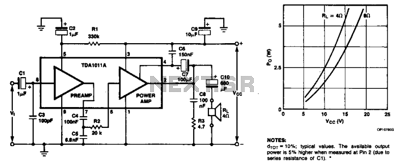
The monolithic integrated audio amplifier circuit is specifically designed for portable radio and recorder applications, delivering up to 4 W into a 4-ohm load impedance. The power output is close to 6 watts RMS. The monolithic integrated audio amplifier circuit...
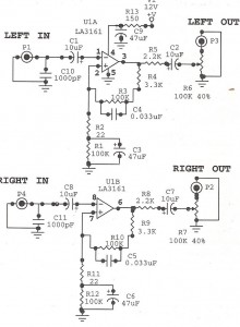
This design addresses the limitations of the microphone preamp in the Sony R91, which clips at low levels, providing only 28mV of headroom for an input that may reach 1800mV, depending on the microphone and volume settings. The design...
Preamplifiers are utilized to amplify low-level signals, such as those from microphones and tape heads, before they are sent to power amplifiers. Power amplifiers typically exhibit lower sensitivity. The frequency response can also be adjusted and optimized at the...
Both transistors should be low noise types. In the original circuit, BC650C was used, which is an ultra-low noise device. These transistors are now hard to find, but BC549C or BC109C are good replacements. The circuit is self-biasing and...
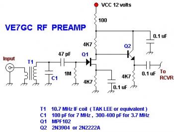
This is a simple VE7GC Popcorn RF preamplifier designed by Dick Pattinson. The circuit features a single tuned circuit at the input stage, allowing direct connection to a mixer or product detector in a straightforward receiver project. Adjustable RF...
This is a simple low-impedance preamplifier circuit diagram used to amplify an audio signal. The circuit operates with a 12V DC power source and is straightforward due to its minimal component count. The low-impedance preamplifier circuit is designed to enhance...