
Remote-sensor-loop-transmitter
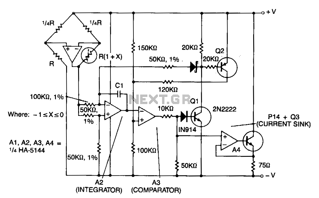
This circuit features amplifier A1 as a sensor amplifier configured in a bridge arrangement. Amplifiers A2 and A3 are set up as a voltage-to-frequency converter, while A4 functions as the transmitter. The entire sensor/transmitter operates directly from a 4 to 20 mA current loop. The bridge configuration yields a linear output corresponding to variations in the sensor's resistance. The voltage at the output of A1 causes the integrator output of A2 to decrease until it surpasses the comparator threshold voltage of A3. Amplifier A3 activates transistors Q1 and Q2. The output of A2 ramps up at a rate nearly equal to its negative slope, with Q2 providing hysteresis for the comparator. Additionally, Q1 and Q2 mitigate fluctuations in the power supply loop voltage. Amplifier A4 and transistor Q3 are arranged as a constant current sink that activates when the comparator current rises. This increase in loop current transmits the frequency of the voltage-to-frequency converter back to the control circuitry.
The circuit operates on a bridge configuration that enhances sensitivity and linearity in measuring resistance changes from the sensor. The output from amplifier A1 is critical as it translates the resistance variations into a corresponding voltage signal. This voltage is then processed by amplifier A2, which acts as an integrator; its output decreases over time until it reaches a predefined threshold set by amplifier A3, which functions as a comparator. When the output of A2 crosses this threshold, amplifier A3 engages, activating transistors Q1 and Q2.
Transistor Q2 plays a crucial role in providing hysteresis, ensuring that the circuit does not oscillate around the threshold voltage, thus stabilizing the output. Concurrently, Q1 and Q2 help maintain a steady voltage level across the power supply loop, reducing the impact of any voltage variations that could affect the performance of the amplifiers.
Amplifier A4 is designed to operate as a transmitter, while transistor Q3 serves as a constant current sink. When the output from the comparator (A3) increases due to rising current levels, Q3 activates, allowing for the transmission of frequency signals back to the control circuitry. This mechanism enables the system to communicate changes in sensor readings effectively, providing a robust solution for applications requiring precise monitoring of resistance changes in real-time. The overall design ensures that the sensor/transmitter is reliable and efficient, capable of functioning effectively within the specified current loop parameters.This circuit shows amplifier Al as a sensor amplifier in a bridge configuration. Amplifiers A2 and A3 are configured as a voltage to frequency converter and A4 is used as the transmitter. This entire sensor/ transmitter can be powered directly from a 4 to 20 mA current loop. The bridge configuration produces a linear output with respect to the changes in resistance of the sensor.
The voltage at the output of Al causes the integrator output A2 to ramp down until it crosses the comparator threshold voltage of A3. A3 turns on Ql and Q2. Al causes the output of A2 to ramp up at a rate nearly equal to its negative slope, while Q2 provides hysteresis for the comparator. 1n addition, Ql and Q2 help eliminate changes in power supply loop voltage. Amplifier A4 and Q3 are configured as a constant current sink which turns on when the comparator current increases.
The resulting increase in loop current transmits the frequency of the VI F converter back to the control circuitry. 🔗 External reference