
Remote-telephone-ringer
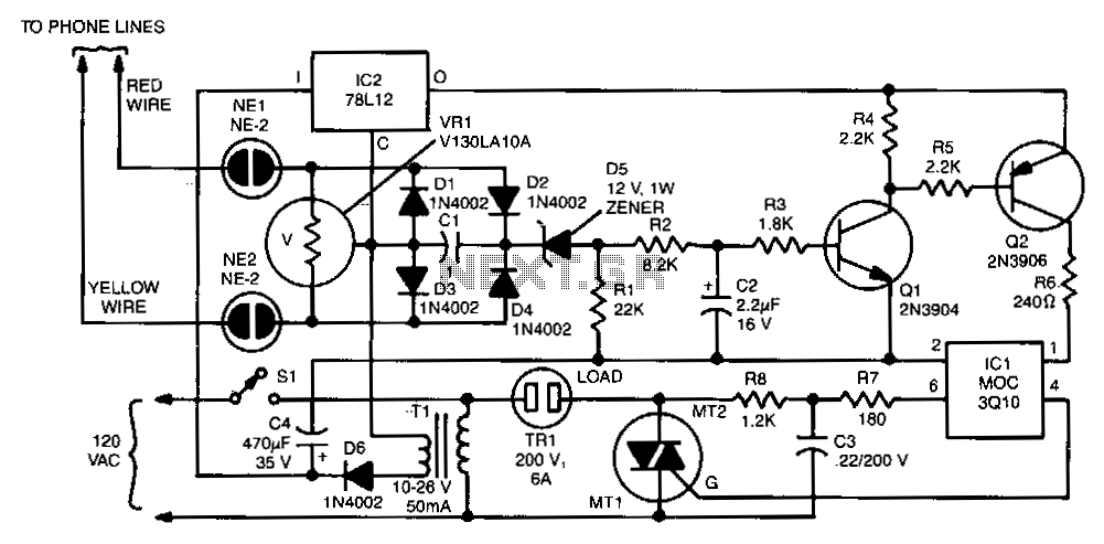
The two neon bulbs will illuminate when the voltage across the ringing circuit exceeds 100 V. These bulbs provide line isolation between the unit and the telephone line. Additionally, they function as a voltage divider for the bridge rectifier composed of diodes D1 through D4. This voltage divider generates a positive voltage that is subsequently applied through diode D5, filtered by resistors R2, R3, and capacitor C2, which results in the conduction of transistors Q1 and Q2. When this occurs, triac TR1 is activated via the optical coupler IC1, turning on the triac and supplying 110 Vac to the load.
The circuit operates as a ringing signal detection and control system, primarily intended for interfacing with telephone lines. The two neon bulbs serve a dual purpose: they not only provide visual indication of the ringing signal but also ensure electrical isolation between the high-voltage telephone line and the low-voltage components of the circuit. This isolation is crucial for protecting sensitive electronics from voltage spikes that may occur on the telephone line.
The bridge rectifier, consisting of diodes D1 through D4, converts the alternating current (AC) ringing signal into a direct current (DC) voltage. The voltage divider formed by the neon bulbs and the rectifier output establishes a reference voltage, which is then routed through diode D5. The filtering stage, involving resistors R2 and R3 along with capacitor C2, smooths out the rectified signal, providing a stable DC voltage to the base of transistors Q1 and Q2.
The transistors Q1 and Q2 act as switches in this circuit. When they are activated by the filtered voltage, they allow current to flow to the gate of triac TR1. The optical coupler IC1 ensures that the control signal is electrically isolated from the high-voltage side of the circuit while providing the necessary drive to trigger the triac. Once TR1 is activated, it allows 110 Vac to flow to the load, effectively controlling the power supplied to the connected device.
This design illustrates a common approach to interfacing AC telephone signals with electronic control systems while maintaining safety and functionality. The use of optical isolation and voltage dividers is a standard practice in such applications to ensure reliability and protection of the circuitry involved.The two neon bulbs will light when more than 100 V is across the ringing circuit. The bulbs provide line isolation between the unit and the telephone line. Finally, they act as a voltage divider for the bridge rectifier made up of D 1 through D4. That voltage divider creates a positive voltage that is then applied through D5, is filtered by R2, R3, and C2, and causes Q1 and Q2 to conduct. When that happens, triac TR1 is fired through the optical coupler IC1; this turns on the triac, which applies 110 Vac to the load. 🔗 External reference