
removable memory card
Three types of removable memory cards are commonly used in mobile phones: the standard SD card, which is larger and used in older models; the miniSD card; and the microSD card, which is the smallest and most prevalent in recent designs. The term "Secure Digital" refers to the SD card, which is a flash-based removable memory card. This card format may also serve functions beyond data storage. Mobile phone manufacturers utilize both SD mode and SPI mode signal functions, which vary according to the design of the mobile phone. To determine whether a memory card uses SD mode or SPI mode, one can inspect the MMC slot socket and count the corresponding pins. In SD mode, all pins are connected, while in SPI mode, some pins are reserved or unused.
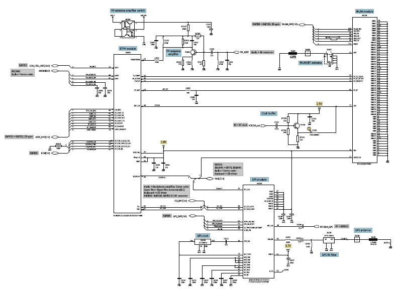
Understanding the operation of the removable memory card circuit in mobile phones and how to troubleshoot related problems, such as the inability to read or detect the memory card, is essential. Additional features like Bluetooth, WLAN, and GPS have become increasingly popular in smartphones. Knowledge of how these circuits function is necessary to keep pace with evolving mobile phone designs. Wireless Local Area Network (WLAN) connects two or more devices using wireless distribution methods, typically spread-spectrum or OFDM radio, facilitating connectivity to the internet through an access point. A typical block diagram illustrates how the clock oscillator provides the desired frequency to the WLAN module. The WLAN module is associated with the Bluetooth transceiver circuit to send and receive data, which is registered with the application processor. This diagram also indicates that the WLAN module requires an RF clock from the RF circuit to operate effectively.
The design of the removable memory card circuit in mobile devices incorporates various components, including the memory card interface, ESD and EMI filters, and the application processor. The memory card interface is responsible for managing data transfer between the memory card and the processor, ensuring compatibility with SD and SPI modes. ESD protection components are typically placed close to the memory card slot to safeguard against electrostatic discharges that could damage sensitive circuitry. EMI filters are implemented to minimize interference from external sources, which is critical in maintaining reliable operation.
The application processor plays a crucial role in interpreting signals from the memory card and executing commands for data read/write operations. When troubleshooting memory card issues, it is important to verify the integrity of the connections, check for any physical damage to the card or slot, and ensure that the filters are functioning properly. By understanding the schematic and operation of the memory card circuit, technicians can effectively diagnose and resolve issues related to memory card functionality in mobile devices.The block diagram below shows how the removable memory card or MMC card connection to other corresponding components. Since the memory card has two signal function operations, the SD mode and SPI mode, the SD mode indicates that all pins of the memory card etherSD card, miniSD cardandmicroSD cardhas a connections while in SPI mode some of the pins are not connected.
See the block diagram below. In mobile phones ESD and EMI filtering were so very important, the connection between the memory card across to the application processor is being filtered or protected by any means of ESD and EMI interruption. The best easy way to identify which one has SD or SPI designed, is by figuring it out on the schematic diagram, and it is so important to know about this for easy troubleshooting and repair memory card related problem issues.
Now, the key reasons in this discussion is also by identifying certain types of ESD-EMI filters being used on every mobile phones designs. Since EMI-ESD filters are most commonly get damaged when it comes to memory card failure problem. In SD mode circuit connection we notice that it`s used an EMI filter with large number of internal filter lines while in SPI mode only a few internal filter lines.
By learning how does the removable memory card works on mobile phone devices. We can easily configure on how to repair if something went wrong when the memory card related problems such as memory card can`t be read, memory card not detected and many other related memory card errors on mobile phones occurred. In mobile phones there are three types of removable memory card being used the first was the SDcard which is so big in size used on some old model cell phones and then comes the MiniSD and the latest is the microSD card which the smaller one and commonly used in most latest designs.
Secure Digital is what SD means, it is a flash based removable memory card. The card format may also be used other device functions in addition to data storage. Mobile phones manufacturers used SD mode and SPI mode Memory card Signal Function, it only varies according on mobile phones designed. You can easily determine which one is SD mode or SPI mode designed. Just figure out the MMC slot socket then count the corresponding pins on it. In SD mode all pins has a connections while in SPI mode some of the pins are reserved and not in used or have no connection in the circuit.
In continuation of this post by learning how the Removable Memory Card Circuit works on mobile phones, and How to troubleshoot and repair memory card problem issues, we can configure which particular mobile phone used the SD mode and SPI Mode signal functions. Additional features such as Bluetooth, WLAN and GPS on Smart phones become more popular in the market.
As a techie you also need to figure out how this circuit works in order for you to catch up a new evolving designed on mobile phones. Wireless Local Area Network (WLAN) links two or more devices using some wireless distribution method (typically spread-spectrum or OFDM radio), and usually providing a connection through an access point to the wider internet.
This gives users the mobility to move around within a local coverage area and still be connected to the network. A typical block diagram below showsbluetooth wlancircuit, this block diagram will tell us how the clock oscillator feeds desired frequency to the WLAN module.
The Wlan is associated is with the bluetooth transceiver circuit to send receive the data from the Wlan module to register it to the application processor. In this diagram shows that the WLAN module also needs the RF clock to make it work, this RF clock comes from the RF circuit.
In other designed aVoltage Cont 🔗 External reference
Related Circuits
Is it possible to use DRAM with microcontroller AVR? Yes, it is possible. Jesperh has proved it. He hooked up a DRAM to a small processor (in this case an Microcontroller Atmel 8515), and handle the RAS/CAS sequencing and...
An electrocardiogram (ECG), also known as EKG (derived from the German term Elektro-Kardiographie), is an electrical recording of the heart utilized in diagnosing heart disease. This application employs a DrDAQ Data Logger to read and store electrocardiograms. British physiologist...
If you are expecting an important visitor but need to step out for a moment, an electronic doorbell memory can be useful to check whether someone rang while you were away. While it cannot confirm if it was the...
This circuit is designed for use with inductive pick-up elements and dynamic microphones. Most soundcards feature a line input and a dedicated input for electret (condenser) microphones. To connect an inductive tape recorder head or a dynamic microphone, an...
The difficulty of connection vga of a videocard to the TV set is, that Frequency of lower case development(display) of the TV set makes 15 KHz, and VGA card - from 31 KHz and is higher. Translation of development(display)...
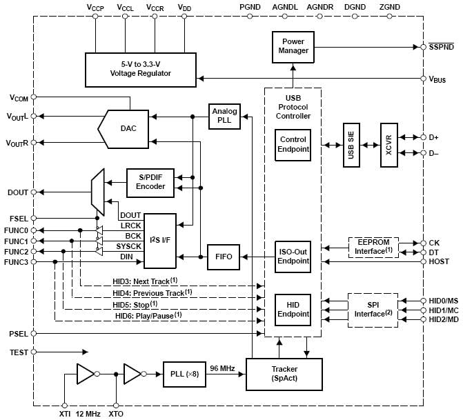
This project involves a high-fidelity external USB sound card or USB headphone system designed for use with PCs or Macs. It utilizes the PCM2706 integrated circuit, which serves as a high-quality, crystal-clear 16-bit stereo digital-to-analog converter (DAC). The PCM2706...
Warning: include(partials/cookie-banner.php): Failed to open stream: Permission denied in /var/www/html/nextgr/view-circuit.php on line 713
Warning: include(): Failed opening 'partials/cookie-banner.php' for inclusion (include_path='.:/usr/share/php') in /var/www/html/nextgr/view-circuit.php on line 713