
Repair Notes of Ten-Tec Corsair 560 Digital Readout
Ten-Tec Corsair 560 Digital Readout module with the top cover removed. The upper circuit board is the bottom side of the TIME BASE 80974 Rev A board. The housing wall ground straps were removed, and a single tined braided strap added near the left edge of the board. Also re-routed is a short green grounding jumper. This replaced a longer edge routed ground jumper. The wooden dowel acts as physical support for the right edge of the board. Ten-Tec Corsair 560 Digital Readout module with the top cover removed, showing the connector board between the upper TIME BASE 80974 Rev A board, and the lower COUNTER LOGIC BD.
80973 board. On the right side of the back edge of the TIME BASE 80974 Rev A board, an RF ground strap ties the two board ground references to gether in a low impeadance manner. This reduces noise, and aids stability. The other path is now a low impedance ground strap near the connector board. This is a better method of grounding for two reasons. Firstly the wide flat physical form of the ground strap is better suited for the creation of low impedance connections.
Secondly it is close to the three ground ports of the connector board. The closer these two ground paths are, the smaller the loop area created by them, and thus the less RF energy can circulate through them, thus reducing noise. The original ground path had a loop defined by the connector board, and two ground points one on either side of the TIME BASE 80974 Rev A board, near to where the dowel is now.
Eye straps were bolted into the walls of the enclosure, and soldered to the edges of the board. This made it difficult to disassemble/assemble, and to work with components on the board. It also drastically increased the loop area of the ground system. However, the real reason the green digit is fairly stable is that Ten-Tec did a good job of designing its PTO (Permeability Tuned Oscillator), which is quite stable. Especially considering that it does not have a crystal reference, and is not digital in any way. Most of the circuitry in the Digital Readout module is high voltage CMOS based (TI: 75xxx, Motorola: 40xxx series).
There are a few 74xx series, 5V devices in the radio but for the most part it uses the 18 volt rated CMOS series devices. The major manufacturers (TI, Motorola, Fairchild, . ) have long since abandoned much of these product lines. Ten-Tec decided to use the radio`s input power rail for much of the logic circuitry. Input power of 13. 2 volts or more would destroy normal 5V level logic devices. Nothing runs particularly fast in this radio. Remember this is mid 1980`s technology. Long before personal computers running in excess of 1 GHz, so the sluggish 6. 5 MHz speed limit of CMOS devices wasn`t a problem. This was another one of those not obviously broken failures. The kind of thing where it is clearly broken but when you take it to someone to fix it, it works fine.
Well. by 2011 it was spending more time bouncing all over, than it was reporting a stable frequency. The PTO and other oscillators in the rig were doing more or less what they should, so the problem must be in the digital readout module. Unfortunately the manual provides no detailed waveforms, indeed the manual makes the usual "There are no user serviceable components" claim for the digital readout module, so some judicious guessing was in order.
But guesses can be a bit wild without information, so an oscilloscope was used to obtain more information. If you follow the lines from the LOAD and STORE ports, into U3, you will see the waveform icons. Like I said, not much to go on. Both of these signals come from the TIME BASE 80974 board. The MK50398N is a "six-decade counter/display decoder", according to a datasheet From MOSTEK Inc. Wikipedia has an entry explaining who MOSTEK was, they are no longer. This counting device is the "brains" of the digital frequency display. By toggling the LOAD and STORE lines properly, the device can generate signals that will form the digits of the LED frequency readout.
This sounds simple enough but doing so over a factor of about 16. 5 (1. 8 MHz through 29. 7 MHz) is a bit more involved. This wide range of counting is why the circuits to provide the user those 6 digits, is spread over two circuit boards. The problem can be thought of this way. roughly. Suppose you set up the counter to provide 6 digits of resolution on the 10m band. That implies you can show 296999 on your display, representing 29. 6999 MHz. Presuming your control pulses can handle this, you are all set. Now suppose you don`t change the control pulses at all but drop the frequency to 1. 799 MHz. You have just reduced the number of events you are counting by a factor of 16. 67, over the same timing. This implies that it now takes 16. 67 times longer for the lowest order decimal digit (going from 00 0001 to 00 0002 takes 16. 67 times longer) to change. The largest count you will now get is 17 999 but you would like to use all 6 of your available digits or 17999 0.
And yet you can`t because your control pulses are set up for a much faster signal, and the bottom decimal digit cannot be resolved. Note that the factor of 16. 67 calls much of the next highest decimal digit into question as well, since each digit can accommodate only 0 through 9 (ten different values), and there are a total of 16.
67 required. Thus the real cost in resolution is two decimal places. A loss of two decimal places is a real problem. Instead of knowing your frequency down to 10 Hz, you only know it to within about 1 KHz. The counter is capable of 6 digits of resolution but you are only getting about 4, on the lowest amateur band of the radio. But look what happens as the display rolls over 9. 99999 to 10. 0. The display capacity is "n. nnnnn", and you need "nn. nnnnn". The upper digit pops off into no where. What is supposed to look like "10. 0000" (you only get 6 digits) looks like "0. 00000". All of a sudden your radio frequency is zero ! If the digital display circuitry behaved this way, which it does not, any frequency within the 560`s capabilities with a number other than "0" in the tens position will be represented by the lower order digits only.
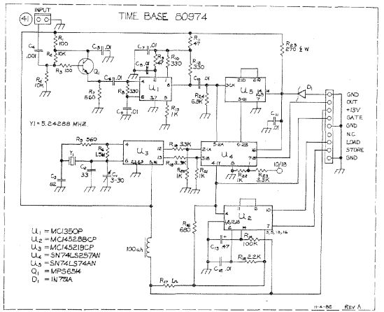
Unfortunately the TIME BASE 80974 schematic hides much of the circuit detail. Some insight may be gleaned from the circuit descriptions of the PTO, and the counter circuitry. However, there is not a detailed description of what the circuits are doing, and why. In the above picture of the TIME BASE 80974 schematic the ICs are represented as blocks, not as logic functions. This means one must consult the datasheet of the respective devices to see the detail of how the designer configured the circuit.
Another problem, in this case, is that the TIME BASE 80974 schematic in the physical manual, is not what is in the Digital Readout module. The module has a TIME BASE 80974 Rev A board installed. The manual`s schematic for the TIME BASE 80974 board has only three ICs. Not Five. Figuring out how the circuit does what it does in detail will be left to another time. At the moment we are trying to solve a specific problem, so how the circuit works in detail will be abandoned for the sake of expediting the present repair effort.
Perhaps a better way to understand this is to take a look at a "good" set of waveforms. The two signals in question are the LOAD and STORE signals. Which can be seen below The above is a screen capture of good LOAD and STORE signals, from the TIME BASE 80974 board. The LOAD signal is on Ch 2 (upper trace). The STORE signal is on Ch 1 (lower trace). The key point is that the upper trace (LOAD signal) had a pulse width that was about as wide as the lower trace in the image above.
This was not good, and probably made it hard for the digital circuitry to capture good counts to be displayed as frequencies. The above is an estimate of the original LOAD signal. It was created using a capture of the correct waveform as a basis. The purpose of this graphic is to suggest how the vertical dashed lines represent a more significant percentage of the pulse width.
The 500 s width of the two dotted/dashed vertical cursor lines, bound the variation of the pulse width of the LOAD signal. As can be seen in the graphic this 500 s bound represents a significant percentage of the overall pulse width.
In this way the graphic suggests the problem the electronics was having. The variation in count value differed significantly, between captures, and thus made it difficult to calculate the frequency. Therefore the display was unstable, and varied widely between captures. The result of this correction in pulse width dramatically improved the stability of the display. With this correction to the pulse width, the digits of the display were stable down to the green colored 100 Hz digit.
Over the years it most likely dried out, and lost most of its capacitance. Consequently the pulse width of the LOAD signal shrank until the display began jumping in value. The capacitor C13 along with the resistor R14 define a time constant for one of U2`s (MC14528B) Multivibrator channels. In this case the channel produces the LOAD signal. These two components dictate the width of this pulse. The MC14528B data sheet has an equation for calculating pulse width on the device. Unfortunately timing longer than 100 s is not supported. Be that as it may, the numbers can be plugged into the equation, This calculated pulse width is about twice the 11.
75 ms measured value. However, recall that the MC14528B data sheet limits its use to 100 s or less in pulse width. In this application the device is being asked to operate at over 1000 times longer than that period. It comes as little surprise then that there is a great deal of difference between the calculated and measured value. The best thing to have done would have been to simply replace C13 with the correct form factor component.
Unfortunately I did not have any small 0. 47 F capacitors on hand. I did have a couple 0. 22 F, 100V polyester capacitors. In the photo below they may look like ceramics but are polyester. The C13 capacitor through hole foot print is just to the left of the IC. Just to the right of the IC are the two 0. 22 F capacitors connected in parallel. A little hot glue provides some mechanical stability. The capacitor C12 was in the way, on the right side of the IC. It was relocated on the back side of the board, so that there would be enough room for the two polyester caps. Capacitor C12 was relocated to the bottom side of the TIME BASE 80974 Rev A board. An edge of one of the 0. 22 F capacitors can be seen peeking out from behind the left edge of the circuit board. When/if a capacitor, with the correct form factor, is available for C13 the paired 0. 22 F capacitors can be removed, and C12 can be put back in its original position. 🔗 External reference
Related Circuits
The issue with this monitor is that the power supply for the vacuum tube backlighting fails. The initial step involves completely disassembling the monitor into smaller components, followed by the careful removal of the gold-colored trays that hold the...
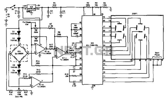
This gauge utilizes an Intersil ICL 7106 A/D converter chip along with an LED display module. It incorporates a Sensym Corp. pressure transducer SX100pn (100 psi full scale) arranged in a Wheatstone bridge configuration, which drives an operational amplifier...

An analog-to-digital converter (ADC) transforms an analog input voltage into a digital value. This circuit illustrates the operation of an ADC, utilizing the ATmega8 microcontroller to control its functionality. The resolution of the converter denotes the number of discrete...
The digital counter circuit described utilizes an infrared signal to detect moving targets, making it suitable for counting small devices on a production line as they move along a conveyor belt. This circuit can also be employed for various...
This digital dice electronic project utilizes a combination of a 555 timer, a 7490 decade counter, a 7483 4-bit binary adder, a 7447 BCD to 7-segment decoder, and a 7-segment display to show the digit. The digital dice project is...
The Clock Controller was designed to be an exemplary of using 'C' language to control timer0 interrupt, 7-segment LED and keypad scanning. It provides 1-bit sink current driving output, for driving a relay, opto-triac, say. Many projects requiring 7-segment...