
Repeating Timer 4
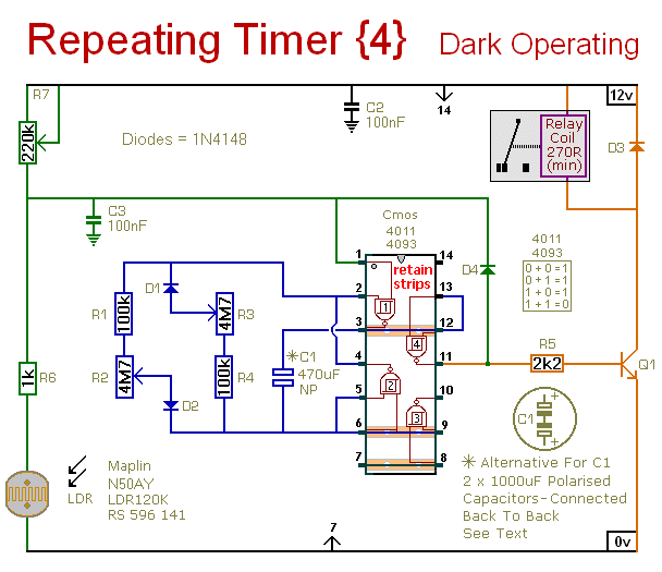
The described circuit functions as a light-activated timer, designed to operate only during periods of low ambient light, such as nighttime. The core of the circuit is a light-dependent resistor (LDR) or phototransistor, which senses the intensity of light in the environment. When the light level falls below a predetermined threshold, set by the variable resistor, the timer circuit is triggered to initiate its operation.
The variable resistor, often referred to as a potentiometer, plays a crucial role in adjusting the sensitivity of the circuit. By altering its resistance, the user can fine-tune the darkness level required to activate the timer. This feature enhances the circuit's versatility, allowing it to be used in various applications, such as automatic outdoor lighting systems, security lighting, or garden lights that only turn on at dusk.
The circuit may include additional components such as a microcontroller or timer IC (e.g., 555 timer) to control the timing duration after activation. The output can be connected to a relay or transistor switch, which in turn controls the power to the load, such as a lamp or other lighting fixtures. The design ensures that the load remains off during daylight hours, thereby conserving energy and extending the lifespan of the lighting components.
In summary, this circuit effectively utilizes a light sensor and adjustable resistance to create a timer that operates exclusively during darkness, making it a practical solution for automated lighting control.This circuit is the opposite of Repeating Timer No.3. Its operation can be limited to the hours of darkness. Again - the variable resistor (preset) lets you choose the level of darkness at which the timer will begin to function.. 🔗 External reference
Related Circuits
The circuit is designed around a 555 oscillator/timer, providing two distinct time periods. The longer time period can be adjusted between approximately 1 to 10 minutes, while the shorter time period is fixed at around three seconds. The operation...
A timer is being developed for circuit training or boxing training. The timer does not require any external input, except for a reset function. The project can be simplified using a microcontroller, such as the PIC12F635, which is cost-effective...
This timer was designed for people wanting to get tanned but at the same time wishing to avoid an excessive exposure to sunlight. A Rotary Switch sets the timer according to six classified Photo-types (see table). A Photo resistor...
On Halloween night, there are often periods of 5, 10, or even 15 minutes when no trick-or-treaters are present. It seemed inefficient to have the fogger continuously emitting fog during these breaks using a standard fogger timer. Therefore, a...
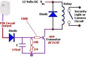
The following circuit illustrates a PIR Sensor Timer Circuit Diagram. Features include a simple design, enhanced accuracy, and efficiency. Components involved are a diode, among others. The PIR (Passive Infrared) Sensor Timer Circuit is designed to detect motion through infrared...
The signal emitted by an IR remote control contains two parts, the control pulses and a modulated carrier wave. The control pulses are used to modulate the carrier, a popular modulation frequency being 36 and 42KHz. The signal is...