
Resonant Mode LED Driver
The resonant mode LED driver circuit operates by utilizing resonant inductive elements to achieve efficient energy transfer while maintaining a stable output current. The primary components of this circuit typically include a resonant inductor, a switching device (such as a MOSFET), and a control circuit that regulates the switching frequency to match the resonant frequency of the inductor-capacitor (LC) tank circuit.
The operation begins with the control circuit initiating the switching of the MOSFET, which allows current to flow through the resonant inductor. As the current builds up, the energy is stored in the inductor until the switch turns off, causing the inductor to release its energy to the LED string. The resonant frequency is critical as it determines the efficiency and effectiveness of energy transfer. By carefully selecting the values of the inductor and capacitor, the circuit can be tuned to minimize losses and maximize the output current delivered to the LEDs.
Additionally, feedback mechanisms are often incorporated to monitor the output current and adjust the duty cycle of the switching device accordingly. This ensures that the LED string receives a constant current, regardless of variations in input voltage or load conditions. The design may also include protection features such as overcurrent protection and thermal management to safeguard the components and enhance the reliability of the circuit.
Overall, the resonant mode LED driver circuit is an efficient solution for driving LED strings, providing not only constant current but also improved energy efficiency compared to traditional linear or switch-mode drivers. This makes it suitable for a variety of applications where consistent LED performance is critical.This is Resonant Mode LED Driver circuit. This circuit is used to give a constant DC current through a string of a given number of LEDs. This circuit uses. 🔗 External reference
Related Circuits
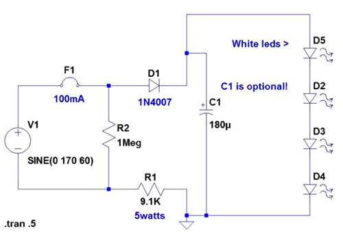
If the AC supply is 220 volts, which resistor should be replaced and with which one? Since 220V is twice that of 110V, the resistance value needs to be doubled accordingly. It is suggested to replace the 9.1kΩ resistor...
A fluorescent tube is connected in an LC resonant circuit consisting of inductor L2 and capacitor C9. The bidirectional breakdown diode VD4 initiates the starting circuit. When AC power is applied, the gate potential of transistor VT2 increases due...
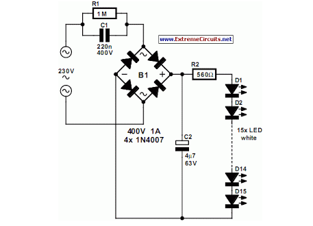
An array of white LEDs can serve as an effective small lamp for the living room. LED lamps are commercially available. LED arrays are increasingly popular for providing ambient lighting in residential spaces. The use of white LEDs in a...

Phase-controlled AC voltage regulator using back-to-back SCRs and diodes, inverse parallel SCRs, and diode-bridge with a single SCR. Input and output voltage waveforms are provided for an input of 250V and an output of 300V. V1 (V5) represents the...

This circuit diagram represents a radio-controlled system, commonly utilized in toy car applications for children. The circuit comprises two main components: the transmitter and the receiver circuits. The transmitter circuit generates radio signals through an oscillator circuit built with...

This is a programmable clock timer circuit that utilizes individual LEDs to display hours and minutes. Twelve LEDs can be arranged in a circle to represent the twelve hours of a clock face, while an additional twelve LEDs can...