
Rev Limiter Circuit
The described circuit utilizes the LM2917 Tachometer IC to monitor engine RPM, providing a robust solution for managing ignition timing in high-performance rotary engines. The integration of an SCR allows for precise control over spark energy, effectively preventing misfires and backfires that could lead to engine damage. The signal shaping network composed of resistors and capacitors ensures that only relevant frequency signals are processed, filtering out unwanted noise that could trigger false readings. The charge pump mechanism is crucial, as it translates the frequency of the engine's RPM into a voltage level that can be easily compared against preset limits. This setup not only enhances the reliability of the ignition system but also allows for adaptability in rev limits, catering to varying operational conditions. The careful design considerations, including the use of a protective resistor, highlight the importance of maintaining sufficient spark energy for the tachometer's operation while simultaneously reducing the risk of excessive engine RPM. Overall, this circuit represents a sophisticated approach to ignition control, emphasizing safety and performance in rotary engine applications.It`s based on an LM2917 and an SCR, which has the very nice side effect of being impossible to generate any mis-timed sparks, a highly desirable attribute for high output rotary engines. When the limit is reached by accelerating to the rev limit, the transition is smooth and causes no backfiring.
(BUT it has the potential to damage the exhaust fro m a backfire if the engine is downshifted and consequently over-revs; due to unburned air/fuel mixture coming from the engine that may be ignited by combustion when the RPMs fall below the limit). The heart of the circuit is a National Semiconductor LM2917 Tachometer IC which detects the engine RPM and when it exceeds a given level the `load` SCRs are turned on which reduces/eliminates the spark energy and hence the engine power.
The input signal comes via the 10k, 22k resistors and C1 (. 02u). This forms a signal shaping network that protects the IC input and filters out any high frequency signals (eg coil ringing). This filtered input is compared against a 0. 6volt reference formed by D1 and it`s 10k resistor. This further serves to minimise false triggering. Now there is a signal which pretty much represents a cleaned up version of what`s happening at the points.
This passes into a "Charge pump" with C2, C3 and the 100k resistor. This converts the frequency of the input signal (i. e. the engine RPM) into a voltage level. From the charge pump, this voltage level is compared with the preset voltage level (the 50k "Set rev limit" potentiometer - the 15k preset associated with this is optional, and sets the absolute maximum rev limit. This is handy if the rev limit is changed depending on the situation). When the tachometer voltage exceeds the limit voltage (i. e. the ENGINE RPM IS OVER THE LIMIT), the transistor in the tachometer IC turns on. When the C122E turns on, it effectively "shorts out" the points. The 4. 7ohm resistor IS REQUIRED. Basically what happens is when the points open and the SCR is turned on the 4. 7 ohm resistor is across the points. This causes the magnetic field inside the coil to collapse only marginally, which in turn generates a much weaker spark than usual.
However, there is still enough signal for the IC to be able to sense the points opening/closing. It did not seem to be able to repeatably restrict RPM (eg when used on different days) to an accuracy of better than 500rpm. I have not investigated exactly why this happens or any possible fixes - and as my electronics knowledge has slipped over the last few years do not intend to.
I think it may be due to the wildly varying voltages in the operation of the ignition system and the relative difficulty of making exact measurements (for the triggering of the timing circuit), there is probably also some thermal effects. 16/3/2001 - Converted all text to new standard (Headings as Heading1, Some sub-headings (e. g. tables) as 14 point normal bold italic, Most text as Normal, Internal page links at top not all uppercase) 11/3/2001 - Minor content update (Spelling mistakes, tidy up).
Removed Word document version of file to avoid virus risk. PG01_02B. GIF edited to change author to Craig`s Rotary Page. Changed from Netscape to FrontPage. Background image changed to PG00_02B. JPG
Related Circuits
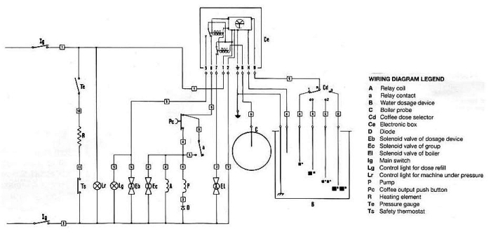
The pump is designed to stop only when the volume set by the four-position selector switch has been reached. However, it will also stop if certain conditions are met. Pressing the brew button (`Pc`) momentarily closes the circuit, sending...
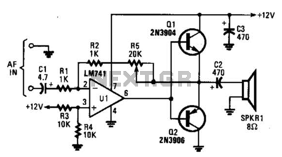
The circuit is designed around an LM741 operational amplifier configured as an inverting amplifier. It is utilized to drive complementary transistors (Q1 and Q2). The feedback loop of the op-amp incorporates the base-emitter junctions of both transistors, which aids...
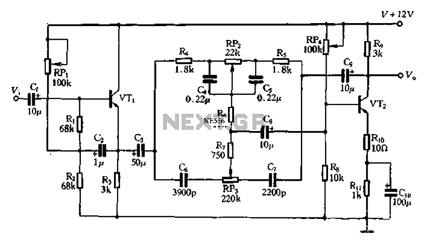
The attenuation circuit is a feedback tone control system that consists of transistors and an RC network. The circuit includes a low tone control potentiometer (RP2) and a treble control potentiometer (RP3). The bass control is influenced by resistor...
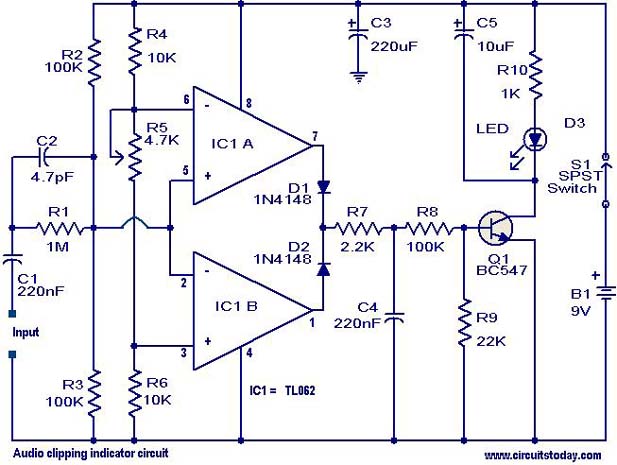
This circuit is designed to detect clipping in a specific waveform. Clipping occurs when the amplitude of a waveform decreases before reaching its expected limit. The circuit activates an LED as an indication that the tested signal is experiencing...
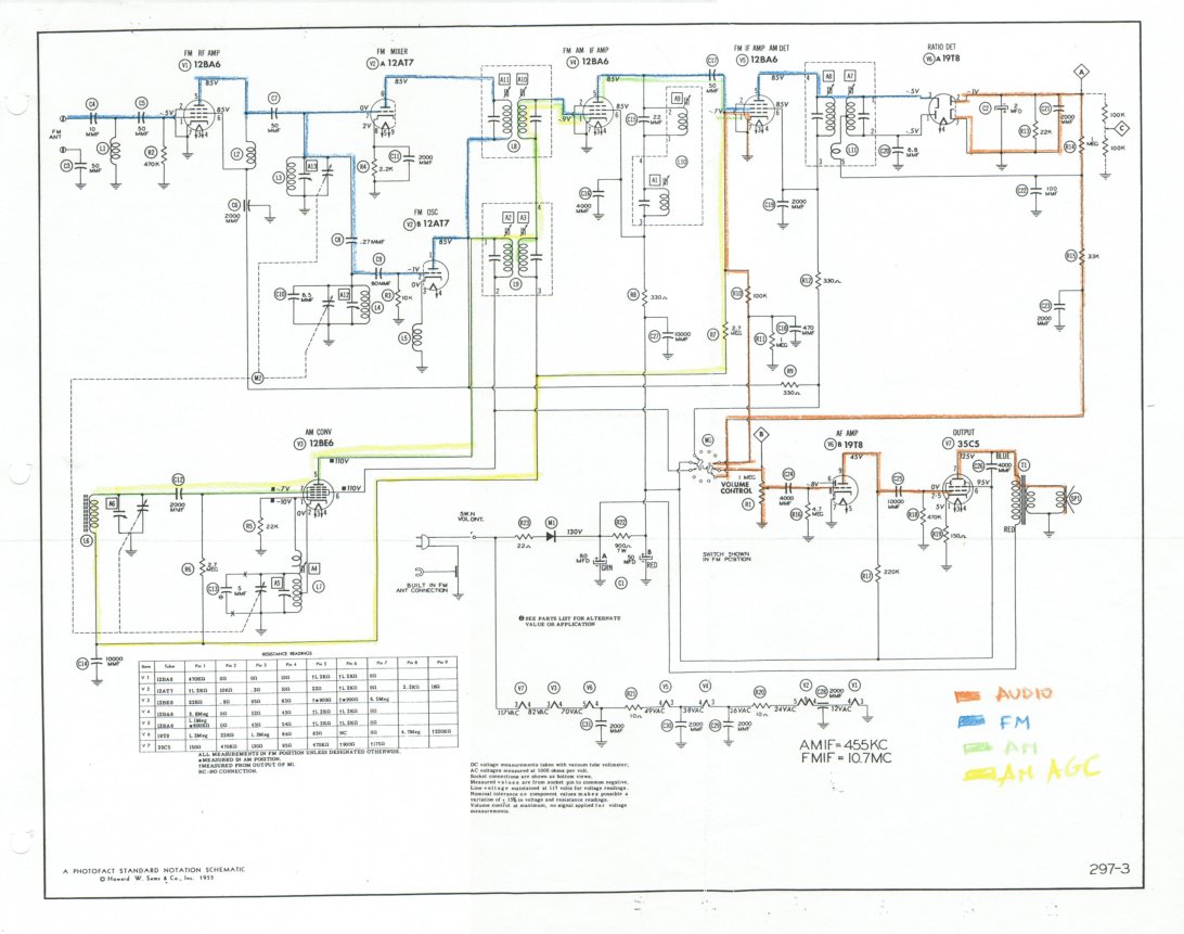
This document outlines the restoration of an antique AM/FM Granco 720 radio. It explores the design of the AM and FM receivers, detailing the alignment of these receivers, discussing repairs, and evaluating the radio's performance. The restoration of antique...
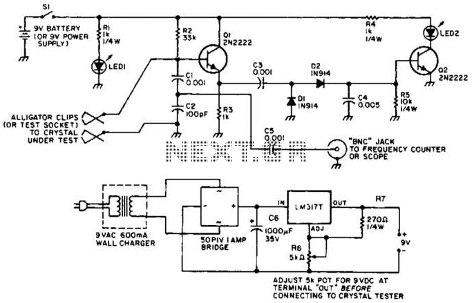
Q1 functions as a Colpitts crystal oscillator. If the crystal being tested is operational, the RF signal is rectified by diodes D1 and D2, which activates Q2 and illuminates indicator LED2. Additionally, LED1 serves as a power indicator. The circuit...
Warning: include(partials/cookie-banner.php): Failed to open stream: Permission denied in /var/www/html/nextgr/view-circuit.php on line 713
Warning: include(): Failed opening 'partials/cookie-banner.php' for inclusion (include_path='.:/usr/share/php') in /var/www/html/nextgr/view-circuit.php on line 713