
RF amplifier circuit diagram
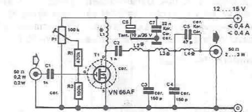
This RF amplifier circuit is designed to enhance the power output of low-power transmitters, enabling them to achieve higher transmission levels suitable for various communication applications. The core component of the circuit is a Field Effect Transistor (FET), which is responsible for amplifying the input signal. The adjustable drain current allows for fine-tuning of the amplifier's performance, making it versatile for different modulation schemes.
The output filter network is critical in maintaining signal integrity by significantly reducing unwanted noise, achieving a suppression level of at least 55 dB. This ensures that the transmitted signal remains clear and free from interference, which is essential for maintaining communication quality.
For linear applications such as Amplitude Modulation (AM) and Single Sideband (BLU), the drain current is specifically calibrated to 20 mA. This setting optimizes the amplifier's linearity, thereby improving the fidelity of the transmitted signal. In contrast, for Frequency Modulation Continuous Wave (FM-CW) applications, the drain current is adjusted to ensure that no current flows through the drain during idle periods. This adjustment is crucial for minimizing power consumption and enhancing the efficiency of the amplifier, with an idle current typically set between 200 mA and 300 mA.
Overall, this RF amplifier circuit offers a practical solution for increasing the power output of small transmitters while maintaining signal quality and operational efficiency across various transmission modes.By making this RF amplifier small power transmitters of 200 mW, can be transformed into a power transmitters reasonable, ranging between 2 and 3 W. The circuit is very simple. Network output filter suppresses noise by at least 55 dB. Amplifier is suitable for almost all types of transmissions, because of the possibility of adjusting the drain curr
ent of FET`s by P1. For linear applications (AM and BLU), drain current must be adjusted to 20 mA. If is used for FM-CW, P1 will be adjusted so that no current will not flow through the drain rest. For this case, the idle current is 200 mA and between 300 mA. 🔗 External reference
Related Circuits
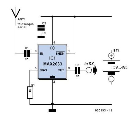
This is a preselector circuit designed for shortwave (SW) receivers, specifically a do-it-yourself (DIY) high-frequency preselector. The circuit employs a modern low-capacitance MOSFET with two gates, which generates a negative inverse reaction through an uncoupled source resistor. When applied...
The objective of Linkwitz's article was to reduce distorted spatial reproduction when listening to recorded stereo music with headphones, addressing the "super stereo" effect where the music appears to originate from within one's head. To eliminate this spatial distortion,...
The VFC62 is a voltage-to-frequency and frequency-to-voltage converter that effectively transforms analog signals into digital signals. The digital output is presented in an open collector format, where the digital pulse repetition rate is directly proportional to the amplitude of...
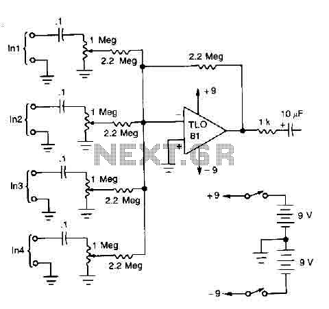
A TL081 operational amplifier is utilized as a high impedance to low impedance converter and as a signal mixer. The input impedance is approximately 1 megohm, while the output impedance is around 1 kohm. The circuit is powered by...
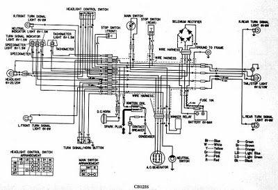
CB125S Wiring Diagram Manual PDF Download. The CB125S Wiring Diagram Manual provides a comprehensive guide for understanding the electrical system of the CB125S motorcycle. This manual includes detailed wiring diagrams that illustrate the connections between various electrical components, such as...
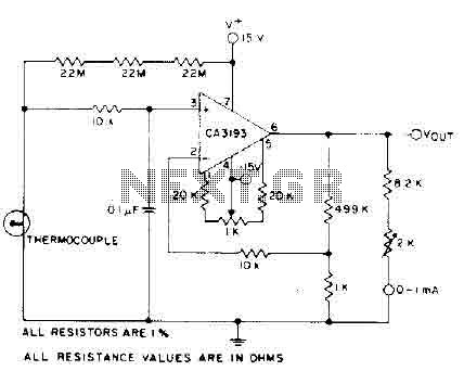
The circuit requires a 15-volt power supply and employs a precision operational amplifier, CA3193 BiMOS, to amplify the generated signal by more than 500 times. Three 22-megohm resistors are utilized to ensure a large-scale output in the event of...