
Fm demodulator
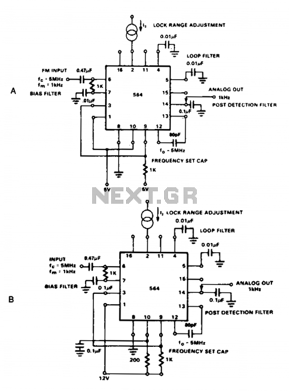
The NE564 is a versatile integrated circuit designed for frequency modulation (FM) demodulation applications. This device operates effectively in both low-voltage (5 V) and standard voltage (12 V) environments, making it suitable for various electronic systems. The AC coupling of the input signal is crucial, as it ensures that only the varying component of the signal is processed, eliminating any DC offset that could distort the demodulated output.
The output signal is taken from Pin 14, which is strategically designed to provide a clean demodulated output. Loop filtering is a critical aspect of the NE564's operation, as it stabilizes the demodulation process and enhances signal integrity. Capacitors connected to Pins 4 and 5 serve to filter out unwanted high-frequency components, while the additional capacitor at Pin 14 further refines the output signal, ensuring that it is free from noise and distortion.
It is essential to consider the conversion gain of the VCO when designing systems that utilize the NE564. The relatively low gain necessitates that the frequency deviation of the input signal be maintained at 1% or higher. This ensures that the demodulated output signal is sufficiently strong for further processing or amplification in downstream circuits. Overall, the NE564 is an effective solution for FM demodulation, provided that the design parameters are carefully adhered to, particularly concerning input signal characteristics and filtering requirements.The NE564 is used as an FM demodulator. The connections for operation at 5 V and 12 V are shown in Figures 21-4A and 21-4B. The input signal is ac coupled with the output signal being extracted at Pin 14. Loop filtering is provided by the capacitors at Pins 4 and 5 with additional filtering being provided by the capacitor at Pin 14. Since the conversion gain of the VCO is not very high, to obtain sufficient demodulated output signal the frequency deviation in the input signal should be 1% or higher. 🔗 External reference
Related Circuits
The TDA3567 is a monolithic integrated decoder designed for the NTSC color television standards. It incorporates all the necessary functions for the demodulation of NTSC signals. Additionally, it features a luminance amplifier and an RGB matrix amplifier. These amplifiers...
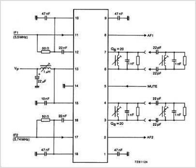
The TBA120 Series integrated circuits (ICs) offer a high-gain limiting intermediate frequency (IF) amplifier and a quadrature coincidence detector in a single package. These ICs are primarily designed for the extraction of television intercarrier sound, which is frequency modulated...
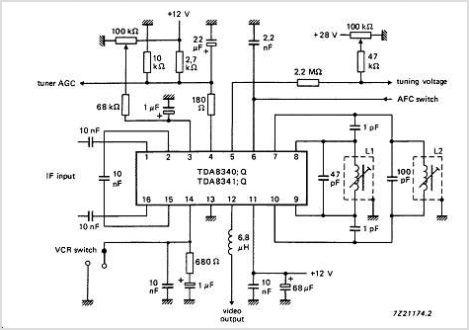
The TDA9813T is an integrated circuit designed for processing vision intermediate frequency (IF) signals and dual frequency modulation (FM) demodulation of sound. It operates with a single reference QSS-IF in television (TV) and video cassette recorder (VCR) applications, specifically...
This demodulator is designed for the quadrature phase-shift keying (QPSK) modulator previously published by the same author in "Novel Low-Cost QPSK Modulator Needs No Adjustments" (Electronic Design, Sept. 16, 2002, p. 92). Utilizing common CMOS logic, it requires no...
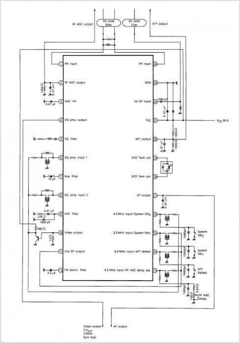
The TA1284FN is a TV tuner integrated circuit (IC) that combines a mixer and oscillator for VHF and CATV bands, a mixer and oscillator for the UHF band, and an intermediate frequency (IF) amplifier into a single chip. It...
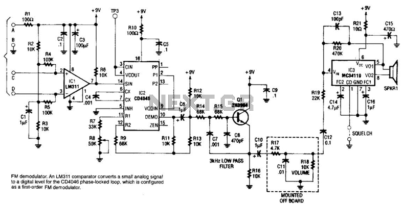
An LM311 comparator converts a small analog signal to a digital level for the DC4046 phase-locked loop, which is configured as a first-order FM demodulator. This demodulator operates with a 50-kHz FM modulated input signal and has applications in...